Download Current Electricity notes , In this post We will Study, Current Electricity Notes & Important Topic for Student to excel in exam.
NCERT/CBSE class 12th Physics notes provided by free-education.in (Wisdom Education Academy).
Here We are providing all subject wise pdf notes to student for their help to get good marks in exam.
In this post you can Download CBSE 2020-21 Physics PDF notes given below by free-education.in to excel in the exam.
www.free-education.in is a platform where you can get pdf notes from 6th to 12th class notes, General Knowledge post, Engineering post, Career Guidelines , English Speaking Trick , How to crack interview and lots more.
Download pdf notes for Current Electricity [Click Below link]
Chapter 3: Current Electricity
Download Previous Year Question Papers
Introduction
- We are going to learn about how the charges which are in motion constitute the current, to study how current is used in our daily life.
- For example: –
- Glowing of bulb by switching on and off the switch.
- All the electrical appliances work when the current passes through them.
- Washing machines, iron box,battery,TV,laptop and so on.
- In this chapter we will be able to give answers for the following questions :-
- How electric current is produced by the movement of charges?
- What are the different properties of current?
- What constitutes the electric current?
- What are the different laws which govern the electric currents?
Electric Current
- Electric current is defined as flow of electric charge.
- It is measured as rate of flow of charge.It means how much charge is flowing with respect to time.
- For example consider a charge of 20Coulomb flowing per second.Then the current will be 20Coulomb/sec.
- Electric current is denoted by I.
- It is written as I=dQ/dt,where dQ is rate of change of charge with respect to time.
- I unit is Amperes (A).
- Direction of current determines from where the current originated and where it will terminate.
- It can be categorised into 2 ways:-Electronic and Conventional Currents.
Electronic current & Conventional current
Electronic current
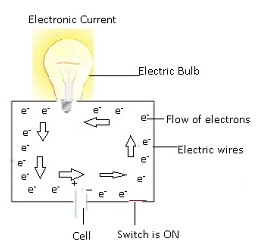
- The electronic current is the flow of current in the direction of flow of electrons.
Conventional current
- The current constituted by the positive charges and opposite to electronic current. This is known as conventional current.
- The conventional current direction is considered whenever we consider the direction of current.
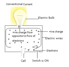
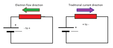
- The direction of current is opposite to the direction of flow of electrons.
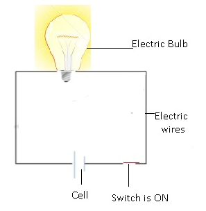
- In any circuit the current is assumed to flow from positive end to negative end.
Simple Electric Circuit
Definition of Ampere:-
- 1 Ampere is unit of measurementof rate of electrons flow or current in an electrical conductor.
- It represents one coulomb of electrical charge (6.24 x 10¹⁸ charge carriers) moving past a specific point in one second.
- Mathematically: – I=dQ/dt
- Consider 1A =1C/1sec; where Unit of charge is coulomb and time is sec.
- => 1A is the amount of current when 1C of charge (i.e. 6.24×10¹⁸ electrons) pass through a point in 1 second.
ElectroMotive force
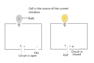
- Emf(electromotive force) of the cell drives the current carriers to move in a specific direction.
- This Emf causes positive and negative charges to flow in a specific direction. As a result current is generated.
- Emf is a misnomer.
- This means from the name it suggests it is a force but actually it is not.It is the potential difference between the two electrodes.
- It is known as force because it acts as initial force to start the flow of charge.
- Emf is defined as maximum work done per unit charge to take charge from one point to another.
- It can be also defined as maximum potential difference between (+ive) and (-ive) electrodes of the cell in an open circuit.
- Emf provides an energy which does the work to move the charge from one point to another.
- As there is potential difference between the two electrodes the charges will flow.
- The charges will tend to flow from higher potential to lower potential.
- There is no conductive path between the electrodes, so charges can’t flow from inside the electrodes.
- That is why a path is created by the circuit by the conducting wires.
- The electrons start flowing towards the (+)ive terminal and as a resultelectric current is generated.
- Similarly (+) ive charges will flow towards the (-)ive terminal of the cell.
- Main reason for the flow of charge is the difference in the potential between the electrodes of the cell.
- This difference in the potential between the electrodes of the cell is known as Emf.
Problem:- The storage battery of a car has an Emf of 12 V. If the internal resistance of the battery is 0.4Ω, what is the maximum current that can be drawn from the battery?
Answer:-
Emf of the battery, E = 12 V
Internal resistance of the battery, r = 0.4 Ω
Maximum current drawn from the battery = I
According to Ohm’s law, E=IR
I=(E/R)=(12/0.4) =30A
The maximum current drawn from the given battery is 30 A.
Difference between EMF and Potential Difference
| EMF | Potential Difference |
| Max potential difference between electrodes in open circuit. | Difference of potential between any 2 points in a closed circuit. |
| It is a source of electric current. | It is just measured between 2 points in a circuit. |
| Emf is independent of resistance in a circuit. | Potential difference is affected by resistance in a circuit.As circuit is closed and current flows through this circuit there will be voltage drop due to resistance R. |
| If in a circuit resistance is added then it won’t affect the EMF between the electrodes as circuit is open. | As circuit is closed and current flows through this circuit there will be voltage drop due to resistance R. |
| EMF is related to the cell only. | P.d. is related to entire closed circuit. |
Current as a scalar
- Current is a scalar quantity.Current does not have direction.
- Current follows the algebraic sum of 2 currents not the vector sum.
- For Example: -If there are 2 wires and resistors areattached with them, then thecurrent will flow from +ive endto–ive end of the wire.
- Whenever the direction of flow of current is specified it will be either by the flow of electrons or the flow opposite to the direction of electrons.
- Always from where the current originate it matters.
- Current flow from positive terminal and move towards the negative terminal.
- Flow of current will be opposite to the flow of electrons.
- To define the direction of the amount of charge thatflows through the particular area,Current densityterm was introduced.
- Current density is a vector quantity
- Current density tells about the amount of charge flowing per unit area and about the direction of the current.
Direct current (DC)
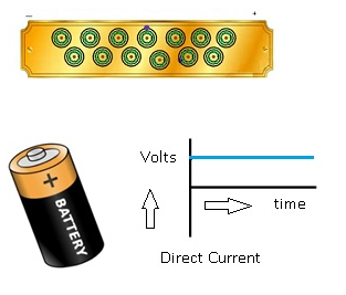
- In DC the electrons always flow in one direction.
- For example: – Current that is generated from a battery.All the electrons will flow towards positive terminal of the battery.
Alternating Current (AC)
- In AC electrons flow back and forth changing direction multiple times in a second.
- Once the electrons reach one end then the polarity of the battery gets reversed.
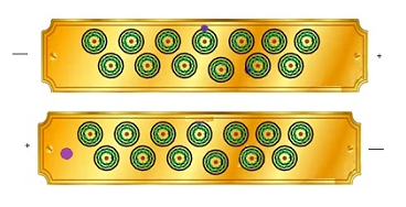
Polarity reverses
Solids as Current carriers
- In solids free electrons carry current. These electrons are free to move around freely.
- For example: –
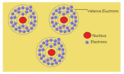
- Consider Copper (Cu) Atomic number = 29.From the electronic configuration (1s2 2s2 2p63s2 3p6 4s1 3d10)of Cu there is 1 electron in the valence shell(outermost shell(4s1)).
- The valence electron is most loosely bound to the nucleus so they have the tendency to come out of atom.
- By giving some energy to the atom the electrons from valence shell will first move out of the shell.
- These valence electrons keep on jumping from one atom to another.
- The movement of free electrons gives rise to current in case of a solid.
Liquids as Current carriers
- In liquids positive and negative ions carries current in liquids.
- An ion is an atom or molecule in which total number of electrons is not equal to the total number of protons,giving it a net positive or negative electrical charge.
- Consider NaCl solution, chlorine has 7 electrons in the valence shell. As chlorine is short of one electron to attain stable atomic configuration, it always has the tendency to gain electron. And Na has one electron in its outermost shell so it has the tendency to lose that electron to become stable.
- As soon as electron loses Na, Nabecomes Na+ ion and when the electron enters chlorine shell, Clbecomes Cl–
- When we apply electric field across this liquid. Na+ move towards the negative end and Cl– move towards positive end.
- Because of movement of these positive and negative ions currentwill be generated.
- Atom becomes ion when it loses or gains anelectron.
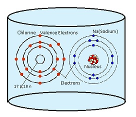
In the above figure Chlorine has 7 electrons in the valence shell and Sodium (Na) has 1 electron in the valence shell. On applying electric field, Cl becomes Cl– ion by gaining one electron and Na loses 1 electron to become Na+.
Gases as Current carriers
- Gases are bad conductors of electricity because they neither have free electrons nor have free ions to conduct current.
- Gases can conduct electricity only if they are ionized.
- Ionization Process:-
- Ionization is a process in which an electron is forcibly extracted from a gas.
- As a result atom will become+ively chargedion.
- By extraction of electron, there will be electrons as well as positively charged ion which can carry current.
- Thereforepositive ions and free electronscarry current in the gases.
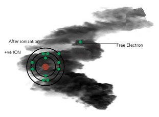
- Gases can be ionized by different ways:-
- External Rays
- For example: – When any radiation falls on a gas they can extract electrons from a gas. As a result free electron and positively charged atom is left behind.
- Electric field and high temperature
- By the application of the electric field electrons can get extracted from the gases forcibly and move towards the positive end of the electric field.
- Electric field and high temperature
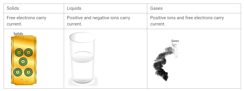
Electric current in Conductors
- Conductors are those substances which allow electricity to pass through them.
Case 1:-Normal condition(Without Battery)
- The free electrons(valence electrons) keep moving randomly.
- These electrons will have some velocity with which they keep on moving randomly inside the conductor. This velocity is known as thermal velocity.
- As this entire motion is random thereforethe average thermal velocity of electrons is 0.
Case 2:- When external electric field is applied.
- When battery is applied the electrons will start moving towards the positive end of the conductor.
- Positively charged ions get attracted towards negative ions, but as these positively charged ions are heavy they don’t move.
- As electrons move towards the positive end they get accelerated.
- As electrons are moving in one direction they will collide with the positively charged ions in the path.
- The extra velocity whatever the electron gained by accelerating will be lost as a part by collision.
- The net result is that the electron acquires a very small amount of velocity. The average of this small velocity which they have acquired is known as Drift velocity.
- Drift velocity is the velocity with which the electrons get drifted towards the positive end of the applied electric field.
- Electrons have 2 velocities- Thermal and Drift.
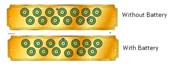
Expression for electrons’ Drift Velocity
- Mathematically:-
- Initially before applying the electric field, electrons are moving randomly such that the average thermal velocity is 0.That isvi=(v1+v2+v3+…+vn)/n=0.
- E = external electric field applied to the conductor.
- Length of the conductor = l and Potential Difference across (+) and (-) ends =V
- From the relationE=V/l as electric field is gradient of potential.
- Each electron will experience a coulomb force because of electric field i.e.F=-eE
- Acceleration of each electron (a) =F/m= (-eE)/me;where me mass of the electron
- But the gain in velocity due to acceleration is lost during collision of electrons with +ive ions.
- After the collision, velocity of an electron =v1 +a τ1 (using v=u+at)
- Where τ1 =time taken by the electron to collide with positive ion,v1=initial velocity.
- Similarly velocity of second electron =v2 +a τ2
- Therefore average of these velocities = Drift Velocity(vd)
- vd = ((v1+a τ1) +(v2 +a τ2)+(v3+a τ3) + …..))/n where n=no of electrons.
- vd =(v1+ v2 +v3+….)/n +a(τ1+τ2+τ3+ ….)/n
- Where (v1+ v2 +v3+….)/n =0= average of thermal velocities of all the electrons.
- vd=aτ ; where τ =average time collapsed since each electronsuffered collision
- e. (τ1+τ2+τ3+….)/n
- Therefore vd =aτ ; using a= -eE/me
- vd =-eEτ /me
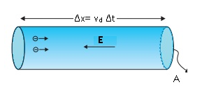
Current in a metallicconductor. The magnitude of currentdensity in a metal is the magnitude ofcharge contained in a cylinder of unitarea and length vd.
How is current related to electrons’ drift velocity?
- Mathematically:-
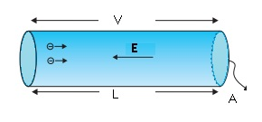
- Consider a conductor of length =L,Area of conductor=A and Potential Difference = V.
- Number of electrons per unit volume(Number Density) =n
- Therefore total number of electrons in the conductor=n x V = nAL
- Charge on total number of electrons =enAL (Equation(i))
- Electric field =V/L; because of electric field electrons start drifting
- Time taken by an electron to cross the conductor=(distance covered/velocity)
- =L/( vd) where vd = drift velocity
- Therefore Current I = (total charge/time) = (enAL)/(L/vd) using (Equation(i))
- I= enAvd =>I ∝ vd
- Even though drift velocity is very small but the number of electrons which are present in the conductor is very huge.
- Thedrift velocityis small but the number of electrons is large so the current is large.
Ohm’s Law
- Ohm’s law is named after the scientist Ohm who gave this law.
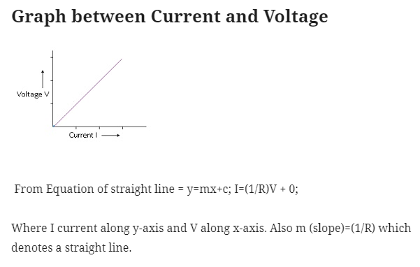
- According to the Ohm’s law current flowing through a conductor is directly ∝ to the potential difference applied between the ends of the conductor.
- This means if the potential difference applied at the ends increases then the current flowing through the conductor also increases and vice-versa.
- Mathematically
- Current flowing through the conductor I ∝ V where V is the potential difference applied at the ends of the conductor.
- Or I=(constant) V where constant = 1/R where R =resistance of the conductor
- => I=(1/R)V
- =>V=IR
Derivation of Ohm’s Law
- Mathematically:-
- vd = (-eEτ/m) equation(i)
- E=-V/L equation(i)
- From Equation(i) and (ii) ;vd =(eVτ)/(mL)
- => V=(vdmL)/eτ ;
- Also I=Anevd
- =>vd=(I)/(Ane) equation(iii)
- Therefore,
- V = (ImL) /(Aneeτ)Using equation(iii)
- =((mL) / (Ane2τ)I)
- =(((ρL)/A))I where ρ= (m/ne2τ)
- Therefore V=RI Hence proved.
Problem:-
A potential difference of 200V is applied across the ends of a conductor of resistance 50 ohms. Calculate the number of electrons flowing through it in one second?
Answer:-
Given V=200V, R=50Ω; By Ohm’s law: – V=IR
=> I=V/R
=>200/50=4A.
I=Q/t = (ne)/t => n= (It)/e
= (4×1)/ (1.6×10⁻¹⁹) = 2.5×10¹⁹
Limitations of Ohm’s law
- Ohm’s law is not true for all objects.
- For example: – Behaviour of diodes. Diode is a device which allows unidirectional flow of current. It does not follow ohm’s law.
- Behaviour of Water Voltammeters.
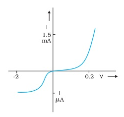
Characteristic curveof a diode. Note the differentscales for negative and positivevalues of the voltage and current.
Problem:- A battery of Emf 10 V and internal resistance 3 Ω is connected to a resistor. If thecurrent in the circuit is 0.5 A, what is the resistance of the resistor? What is the terminalvoltage of the battery when the circuit is closed?
Answer:- Emf of the battery, E = 10 V
Internal resistance of the battery, r = 3 Ω
Current in the circuit, I = 0.5 A
Resistance of the resistor = R
The relation for current using Ohm’s law is, I= (E/R+r)
R+r = (E/I) = (10/0.5) =20Ω
Therefore R=20-3=17Ω
Terminal voltage of the resistor = V
According to Ohm’s law,
V = IR
= 0.5 × 17
= 8.5 V
Therefore, the resistance of the resistor is 17 Ω and the terminal voltage is8.5 V.
Resistance
- Resistance is the property that resists flow of current.
- From Ohm’s law: – V=IR where R=resistance of the conductor.
- If huge amount of current flows through a circuit it will produce huge amount of heat which can damage the circuit.
- Resistance helps to avoid damage to the circuit when huge amount of current flows.
- Resistance will control the flow of current.
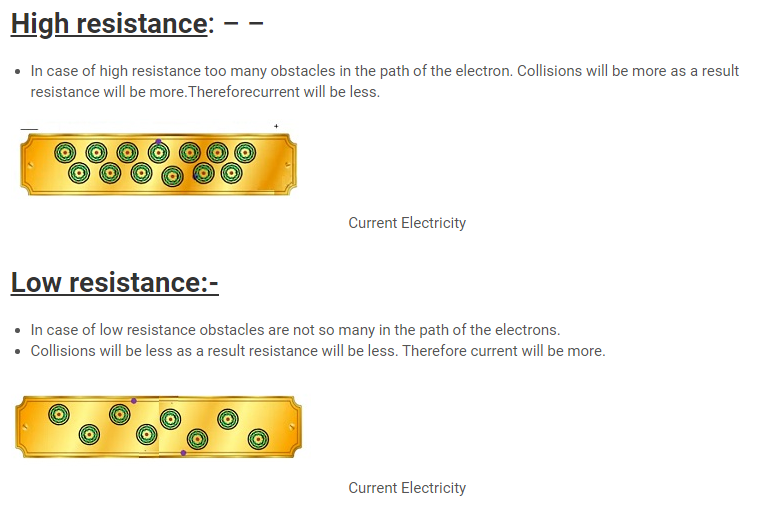
- When we apply some external field the free electrons will start moving towards the positive end.
- They will keep colliding with the positive ions here and there.These collisions give rise to resistance.Greater thecollision more is the resistance and vice-versa.
Expression for resistance
- From Ohm’s law: V=IR => R=V/I
- Where I =current flowing through the conductor.
- R=(V/enAvd) ; Using Equation(i) I= enAvd
- where n=number density, A=area of conductor, vd=drift velocity ,e=charge on electron,m= mass of the electron
- =>R=(V/(enA)) x (m/(eEτ)) ;
- Using vd= ((eEτ)/m)
- where τ=time elapsed between each successive collisions
- => ((El)/(enA)) x((m)/eEτ)) ;
- Using E=V/l
- where V=potential difference and l=length
- By solving, R =(ml)/(ne2τA)
- =>This term (m/ne2τ) depends on the material. It can be taken as constant for specific material.
- This constant is known as ρ.
- Therefore R= ρ (l/A). This ρ is known as resistivity or specific resistance of the conductor.
- Using E=V/l
- Using vd= ((eEτ)/m)
From Equation R= ρ (l/A) the factors on which resistance depends:-
- Length of the conductor. R∝
- If length increases the resistance also increases.
- Consider if the length of the conductor increases then electrons have to travel more distance to reach positive end.
- There will be more obstacles as a result resistance will increase.
- Cross-sectional area of conductor. R∝(1/A).
- If more cross-sectional area resistance will be less and vice-versa.
- If the cross sectional area is increased the obstacles will remain the same but the electrons will get more space to move freely without colliding.
- So there will be fewercollisions therefore resistance tends to decrease.
- Nature of the material of conductor.ρ
- ρ depends on number density(n), mass of the conductor(m), relaxation time between each successive collisions(τ) and charge on the conductor(e).
- Temperature of the conductor.
How resistance varies with temperature?(For metals)
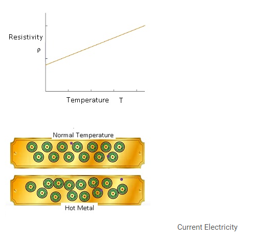
- With increase in temperature the random motion of molecules increases.
- Initially the metal atoms are at rest but when the temperature is increased the metal atom starts vibrating as a result collision between metal atom and free electrons increases and as a result resistance increases.
- Experimentally it was found:-
- Rt=R0(1+α t +β t2)
- Where Rt=resistance at any temperature t.
- R0 =resistance at temperature 0.
- As temperature was very less therefore β t2 is neglected.
- Therefore Rt=R0(1+α t) where α is known as temperature coefficient of resistance.
- α = (Rt – R0)/ (R0t). => If α is (+) ive this means Rt>R0 vice versa.
- Conclusion:-
- α is positive for conductors.
- α is negative for insulators/semiconductors.
- Conclusion:-
- Rt=R0(1+α t +β t2)

Problem:- Aheating element using nichrome connected to a 230 V supply draws an initial current of 3.2 A which settles after a few seconds toa steady value of 2.8 A. What is the steadytemperature of the heating element if the room temperature is 27.0 °C? Temperature coefficient of resistance of nichrome averaged over the temperature range involved is 1.70 × 10⁻⁴ °C −1?
Answer:- Supply voltage, V = 230 V
Initial current drawn, I1 = 3.2 A
Initial resistance = R1, which is given by the relation,
R1 =V/I =230/3.2 =71.87Ω.
Steady state value of the current, I2 = 2.8 A
Resistance at the steady state = R2, which is given as
R2 =230/2.8 = 82.14Ω.
Temperature co-efficient of nichrome, α = 1.70 × 10⁻⁴ °C −1
Initial temperature of nichrome, T1= 27.0°C
Study state temperature reached by nichrome = T2
T2 can be obtained by the relation for α,
α= (R2 – R1)/ (R1(T2 – T1))
(T2 – 27)0C = (82.14 – 71.87)/ (71.87×1.7×10-4))
(T2 – 27)0C =840.5
T2 = 840.5 + 27
T2 =867.50C
Therefore, the steady temperature of the heating element is 867.5°C.
Problem:- A silver wire has a resistance of 2.1 Ω at 27.5 °C, and a resistance of 2.7 Ω at 100 °C. Determine the temperature coefficient of resistivity of silver.
Answer:- Temperature, T1 = 27.5°C
Resistance of the silver wire at T1, R1 = 2.1 Ω
Temperature, T2 = 100°C
Resistance of the silver wire at T2, R2 = 2.7 Ω
Temperature coefficient of silver = α
It is related with temperature and resistance as
α = (R2 – R1)/(R1(T2 –T1))
= (2.7 – 2.1)/ (2.1(100-27.5)) =0.0039°C−1
Resistivity
- Resistivity is also known as specific resistance.
- It is the resistance of the specific material; also it is specific to a material.
- R=ρ, If A and L =1 in Equation R= ρ (L/A).
- Resistivity is defined as resistance of unit length and unit area of a conductor.
- Greater the resistivity,greater the field needed to develop a given current density.
- Consider 2 objects A and B and ρ of A is very high and ρof B iscomparatively low.
- If we apply electric field E to B, then the same amount of current I is produced.
- And if same amount of electric field is applied to material A, the same amount of current (i)won’t be produced as its resistivity is more than B.
- =>(i)<(I).
- In order to have more current more electrons should flow, the obstacles should be less.
- This implies if resistivity is very high then the resistance will be very high as a result current produced will be less.
- To overcome more resistivity more electric filed is applied.
- Resistivity for perfect conductors is 0.In perfect conductors there is no resistance at all.
- Resistivity for perfect insulators is infinite.There are so many obstacles as a result resistance is more so current cannot flow at all.
- Resistance tells about the resistance of the conductor as wholewhereas resistivity tells about the resistance of a specific material.
Resistivity variation with Temperature-Metals
- Case 1:- Normal temperature
- At normal temperature the electrons are free to move the resistance is not so much as a result some current is flowing in the conductor.
- Case 2:- Hot Metal
- As the temperature is more the metal atoms also start moving randomly.
- As a result collisions will be more as they face more obstacles as a result resistivity increases.
- As collisions are more frequent therefore the average time between the collisions decreases as a result τ decreases.
- Therefore drift velocity decreases and as a result current decreases.
Resistivity variation with Temperature-Non Metals
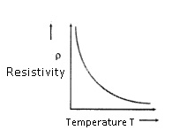
- In case of non-metals resistivity decreases with increase in temperature.
- In metals there will free electrons in the valence shell but in case of non-metals all the electrons are tightly bound to nucleus. Free electrons are not present for conduction.
- But when the temperature is increased the atoms start moving away from the nucleus.
- When temperature increases more electrons are available for conduction as they set themselves loose from the atom.As resultconductivityincreases as the temperature increases.
- Therefore resistivity decreases with increase in temperature.
Problem:-
A wire is stretched to make it 0.2% longer. What is the percentage change in resistance?
Answer:-
Initial length l, Area =A and Resistance =R.
Final l’= l+0.2%l
=l+ (0.2/100) l
=1.002l
Area = A’, Resistance =R’
Volume remains constant.
Al=A’l’ => A’ =Al/l’ = (Al)/ (1.002l)
R’=(ρl’)/A’
Percentage change in resistance = ((R’-R/R) x 100) x100%
= ((ΔR/R) x100) %
ΔR = R’ – R =(ρ(l1/A1)) – (ρ(l2/A2)) = ρ((1.002l)/ (A/0.002)) – ρl/A
=(ρl)/A [(1.002)2 -1] = R x0.004
Therefore, ΔR/R =0.004
Therefore, the temperature coefficient of silver is 0.0039°C−1.
Problem:-
A negligibly small current is passed through a wire of length 15 m and uniform cross-section 6.0 × 10⁻⁷ m2, and its resistance is measured to be 5.0 Ω. What is the resistivityof the material at the temperature of the experiment?
Answer:-
Length of the wire, l =15 m
Area of cross-section of the wire, a = 6.0 × 10⁻⁷ m2
Resistance of the material of the wire, R = 5.0 Ω
Resistivity of the material of the wire = ρ
Resistance is related with the resistivity as
R= ρ (l/A)
Ρ = (RA)/ (l)
= (5x6x10-7)/15 =2×10⁻⁷ Ω m
Therefore, the resistivity of the material is 2 × 10⁻⁷ Ω m.
Problem:-
A wire of resistance 5Ω is drawn out so that its length is increased by twice its original length. Calculate its new resistance?
Answer:-
Initially R=5Ω, Length=l, Area =A
Final Resistance R’, l’=l+2l, Area =A’
=> Al =A’l’
A’ = (Al)/l’ = (Al)/ (3l) = A/3
R’=(ρl’)/A =ρ (3l)/ (A/3)
= ρ (l/A) 9 =9(ρl)/A
=9R =9×5Ω
R’=45Ω
Current density
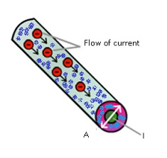
- Current density is defined as current flowing per unit area provided the area is held normal to the current.
- Current density is a property which describes at a specific point of the conductor.
- Consider a conductor and to know what amount of current is flowing through a particular point of the conductor at particular time.
- Not only the magnitude but the orientation of the area plays an important role.
- It is denoted by J.
- J=I/A where A=area vector
- It is a vector quantity.
- Current density changes as the orientation of the area changes.
- Mathematically:-
- J=dI/dA where dI=change of current with unit area.
- J.dA = dI ;=>JdAcosθ =>dI
- When dA is perpendicular to J then ,θ =900 => cosθ =1
- JdA=dI=> I=JA
- J=I/A .This is true only when the area vector is held normal to the direction of the current.
Electrical Conductance and Conductivity
- Electrical Conductance is opposite to resistance.
- Conductance means something which conducts the current. Greater the resistance lesser the conductance and vice-versa.
- Unit is mho/Siemen (S)
Conductivity
- Conductivity is the inverse of resistivity.
- It is denoted by σ.
- Unit :mho m-1/Sm-1
Microscopic form of Ohm’s law
- It is known as microscopic as it tells about the phenomenon which takes place inside the conductor.
- Current density ,J=σE
- J=I/A => I= Anevd ,therefore J=(Anevd)/A
- => nevd = ne(eEτ/m) using vd = (eEτ/m)
- =(ne2Eτ)/m
- Therefore J=(ne2Eτ)/m using ρ=m/(ne2τ)
- J=(1/ρ)E
- J=σE; this is the alternative form of Ohm’s law.
Problem:-
In the Bohr model of Hydrogen atom, the electron circulates around the nucleus in a path 5.1×10⁻¹¹ at a frequency of 6.8×10¹⁵ revolutions per second.Calculate the equivalent current?
Answer:-
Radius r =5.1×10⁻¹¹ m
Frequency f=6.8×10¹⁵ rev/sec
I=Q/t => e/t; where t is the time taken by electron to complete 1 rev.
t= (Distance travelled in 1revolution)/Speed = (2πr)/v
=>v=rω where ω=angular frequency.
=>v=r2πf.
After calculations and simplifications, t=1/f,
I=ef =1.6×10-19 x 6.8×1015 =1.088×10⁻³A
Problem:-
In a discharge tube, the number of hydrogen ions drifting across a cross section per second is 1×10¹⁸, while the number of electrons drifting in the opposite direction across another cross-section is 2.7×10¹⁸ per second. If the supply voltage is 230V, what is the effective resistance of the tube?
Answer:-
Effective resistance=V/I where I =current through cross-section.
I=Q/t = (ne+ np) e/t= ((2.7×10¹⁸+1×10¹⁸)1.6×10⁻¹⁹)1sec =0.592A
Therefore Effective resistance =V/I =230/0.592= 3.9×10²Ω.
Problem:-
Two wires of equal length, one of aluminium and the other of copperhave the same resistance. Which of the two wires is lighter? Henceexplain why aluminium wires are preferred for overhead power cables.(ρAl = 2.63 × 10⁻⁸ Ω m, ρCu = 1.72 × 10⁻⁸ Ω m, Relative density ofAl = 2.7, of Cu = 8.9.)
Answer:-
Resistivity of aluminium, ρAl = 2.63 × 10⁻⁸ Ω m
Relative density of aluminium, d1 = 2.7
Let l1 be the length of aluminium wire and m1 be its mass.
Resistance of the aluminium wire = R1
Area of cross-section of the aluminium wire = A1
Resistivity of copper, ρCu = 1.72 × 10⁻⁸ Ω m
Relative density of copper, d2 = 8.9
Let l2 be the length of copper wire and m2 be its mass.
Resistance of the copper wire = R2
Area of cross-section of the copper wire = A2
The two relations can be written as:
R1=(ρ1l1)/A1 (i)
R2=(ρ2l2)/A2 (ii)
It is given that, R1=R2
(ρ1l1)/A1 = (ρ2l2)/A2
And,l1 = l2
Therefore (ρ1/A1) = (ρ2/A2)
= (A1/A2) = (ρ1/ρ2) =2.63×10⁻⁸/ (1.72×10⁻⁸)
= (2.63/1.72)
Mass of the aluminium wire,
m1 = Volume × Density
= A1l1 × d1 = A1 l1d1 … (iii)
Mass of the copper wire,
m2 = Volume × Density
= A2l2 × d2 = A2 l2d2… (iv)
Dividing equation (iii) by equation (iv), we obtain
= (m1)/ (m2) = (A1 l1d1)/ (A2 l2d2)
For l1=l2
=m1/m2 = (A1d1)/ (A2d2)
For (A1/A2) = (2.63)/ (1.72)
=m1/m2 =(2.63 x 2.7)/ (1.72 x 8.9)
=0.46.
It can be inferred from this ratio that m1 is less than m2. Hence, aluminium is lighterthan copper.Since aluminium is lighter, it is preferred for overhead power cables over copper.
Resistors
- Resistors are objects which resist the flow of current.
- There are 2 types of resistors:-
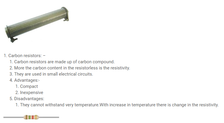
- Wire bound resistors:-Wire bound resistors are made up of alloys.
- Wires of alloy are wound over and over again to form a resistor.
- They are used in car braking system, railway track system, etc. becausethe resistivity of an alloy does not change with temperature.
- They are insensitive to temperature.
Resistor colour codes
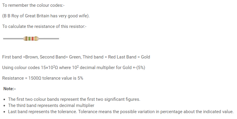
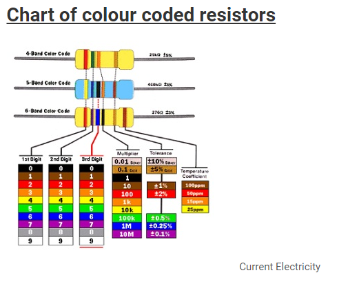
- To know the resistance of a resistor colour coding is done.
- Carbon resistors have different colour bands or different colour rings which have specific value.
| Colour | Number | Tolerance |
| Black | 0 | |
| Brown | 1 | |
| Red | 2 | |
| Orange | 3 | |
| Yellow | 4 | |
| Green | 5 | |
| Blue | 6 | |
| Violet | 7 | |
| Grey | 8 | |
| White | 9 | |
| Gold | 5% | |
| Silver | 10% | |
| No colour | 20% |
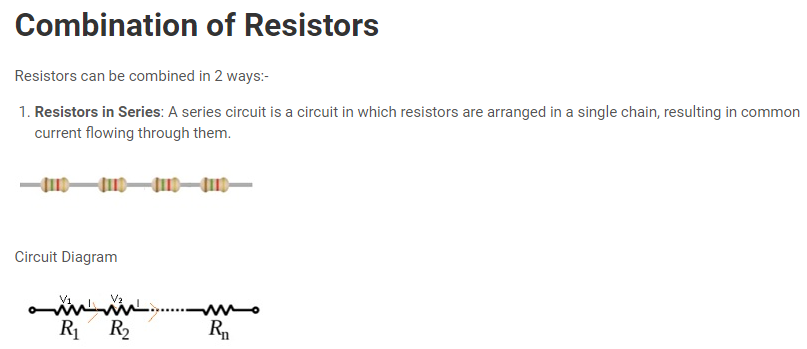
- ‘N’ number of resistors can be joined together.
- As all the resistors are connected to each other as a result same amount of current flows through each resistor.
- But the Potential difference will be different in each resistor.
- Consider current flowing through all the resistors =I,Resistance across first resistor=R1.
- Potential difference across resistor R1is V1, V1=IR1(By ohm’s Law)
- Similarly V2=IR2, V3= IR3 and so on.
- Therefore Total Voltage V=V1+V2+V3+….. +Vn
- IRequivalent =IR1+IR2+IR3+…. +IRn where Requivalent is the equivalent resistance of the circuit.
- =>Requivalent =(R1+ R2+ R3+….+Rn)
- Therefore if the resistances are connected in series then the total equivalent resistance of the circuit is equal to the sum of all the resistors in the circuit.
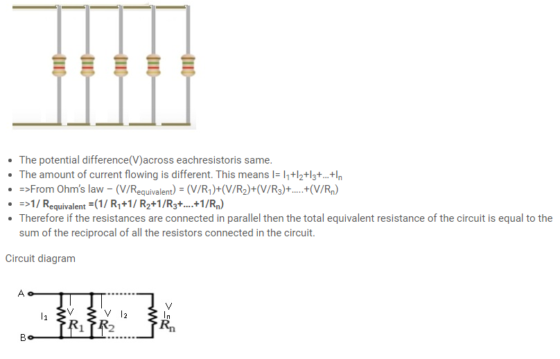
- Resistors in Parallel:- A parallel circuit is a circuit in which the resistors are arranged with their heads connected together, and their tails connected together.
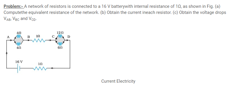
Answer:- (a) The network is a simple series and parallel combination ofresistors. First the two 4Ω resistors in parallel are equivalent to aresistor = [(4 × 4)/(4 + 4)] Ω = 2 Ω.
In the same way, the 12 Ω and 6 Ω resistors in parallel areequivalent to a resistor of
[(12 × 6)/(12 + 6)] Ω = 4 Ω.
The equivalent resistance R of the network is obtained bycombining these resistors (2 Ω and 4 Ω) with 1 Ω in series,that is,
R = 2 Ω + 4 Ω + 1 Ω = 7 Ω.
(b) The total current I in the circuit is
I=E/(R+r) =16V/(7+1) Ω =2A.
Consider the resistors between A and B. If I1 is the current in oneof the 4 Ω resistors and I2 the current in the other,
I1 × 4 = I2 × 4
that is, I1 = I2, which is otherwise obvious from the symmetry ofthe two arms.
But I1 + I2 = I = 2 A. Thus,
I1 = I2 = 1 A
that is, current in each 4 Ω resistor is 1 A. Current in 1 Ω resistorbetween B and C would be 2 A.
Now, consider the resistances between C and D. If I3 is the currentin the 12 Ω resistor,
and I4 in the 6 Ω resistor,
I3 × 12 = I4 × 6, i.e., I4 = 2I3
But, I3 + I4 = I = 2 A
Thus, I3 = (2/3) A,I4= (4/3)A
that is, the current in the 12 Ω resistor is (2/3) A, while the currentin the 6 Ω resistor is
(4/3) A.
(c) The voltage drop across AB is
VAB = I1 × 4 = 1 A × 4 Ω = 4 V,
This can also be obtained by multiplying the total current betweenA and B by the equivalent resistance between A and B, that is,
VAB = 2 A × 2 Ω = 4 V
The voltage drop across BC is
VBC = 2 A × 1 Ω = 2 V
Finally, the voltage drop across CD is
VCD = 12 Ω × I3 = 12 Ω × (2/3) A=8V.
This can alternately be obtained by multiplying total currentbetween C and D by the equivalent resistance between C and D,that is,
VCD = 2 A × 4 Ω = 8 V
Note that the total voltage drop across AD is 4 V + 2 V + 8 V = 14 V.
Thus, the terminal voltage of the battery is 14 V, while its Emf is 16 V.
The loss of the voltage (= 2 V) is accounted for by the internal resistance1 Ω of the battery [2 A × 1 Ω = 2 V].
Cells, Internal resistance, Emf
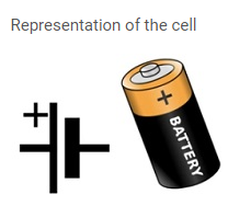
- A cell is a device which generates electricity by using chemical energy.
- A cell consists of electrodes and electrolytes.
- Electrodes are the conductors through which current can pass.They can be in a form of wire or rod or plates.
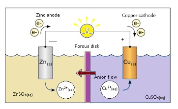
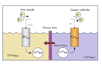
- In case of galvanic cell as shown in the figure there are 2 electrodes in the form of rod.One is Zinc and other is copper.
- Electrolyte is a substance where free ions are present because of which it can conduct electricity.
- In galvanic cell electrolyte is ZnSO4 and CuSO4.
- Zn has the tendency to become Zn ion i.e. to lose 2 electrons present in the valence shell.
- Zn-> 2e– + Zn2+
- Cu ion has the tendency to gain electron and become Cu and stick to electrode.
- Cu2++2e– -> Cu
- If Zn and Cu are joined together with a help of conducting wire,the electrons will flow from Zn to Cu.
- Flow of electrons constitute current. Current will flow from Cu electrode to Zn electrode.
- Note:-
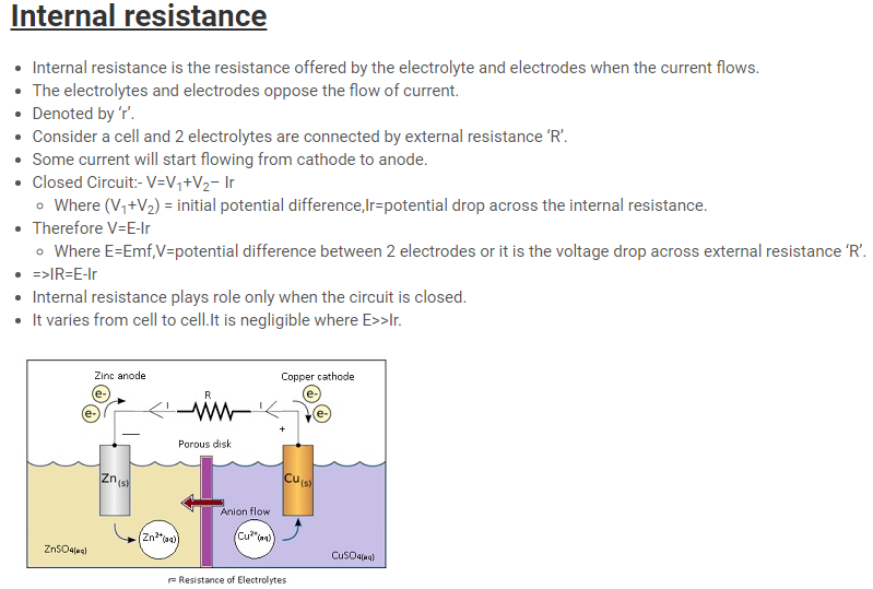
- Current flows from cathode to anode through external circuit.
- Current flows from anode to cathode through electrolyte.
EMF
- Emf is defined as the potential difference between electrodes when there is no current in the cell(cell is in open circuit).
- Emf of the cell initiates the flow of current in the cell.
- The following reactions will take place whether the circuit is open or closed.
- Zn-> 2e– + Zn2+
- Cu2++2e– -> Cu
- Amount of energy involved by Zn to lose 2 electrons is given by potential.
- Potential is the energy per unit coulomb.There is potential associated with Zn and Cu.
- The potential of Zn is higher w.r.t. to electrolyte = V1Thepotential of Cu is lower w.r.t to electrolyte = V2 volt.
- Therefore Emf= potential difference between 2 electrodes(Zn and Cu).
- Emf =V1 – (–V2) =V1+V2
Cells in Series

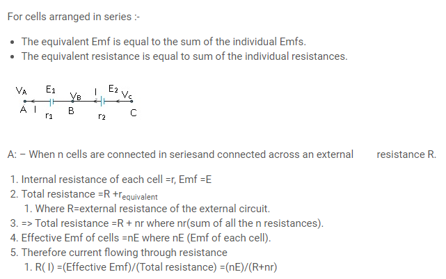
- Let the Emf of first cell = E1 and Emf of second cell = E2.Consider 3 points A, B and C as shown in the figure.
- The potential at point A= VA, potential at point B=VB and potential at point C=VC.
- Assuming circuit is closed as a result there will be some flow of current,resistance will be offered by the cell itself.
- Internal resistance of first cell =r1 and Internal resistance of second cell=r2.
- Equation for potential difference E1(first cell):-
- For an open circuit: – potential difference between points A and B (VA-VB) = potential difference between the 2 electrodes.
- Therefore VA-VB =E1 –Ir1 (Equation(i))
- Where Ir1 = voltage drop across the internal resistance.
- Similarly for equation for potential difference E2(second cell):-
- VB– Vc =E2 –Ir2 (Equation (ii))
- Adding (i) and (ii), VA – Vc =E1 –Ir1 + E2 –Ir2
- => VA – Vc =E1+ E2 –I(r1+r2) (Equation(iii))
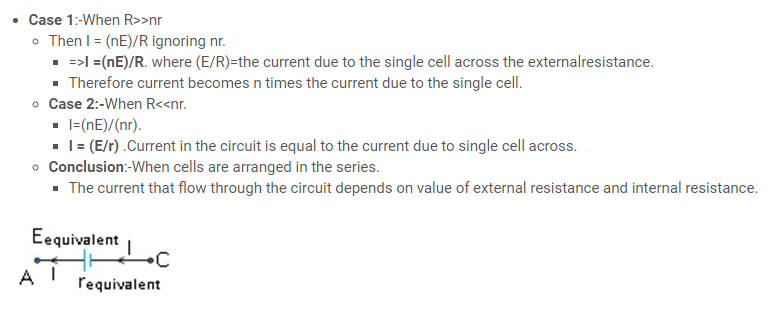
- Assuming if there are only 2 cells then the Emf = Eequivalent= (E1+ E2) and resistance=requivalent= (r1+r2).
- =>VA – Vc = Eequivalent–Irequivalent(Using (iii)) (Equation(iv))
- By comparing RHS of equations (iii) and (iv)
- Eequivalent = E1+ E2andrequivalent = r1+ r2
Problem:-
Three resistors 1 Ω, 2 Ω, and 3 Ω are combined in series. What is the totalresistance of the combination? b) If the combination is connected to a battery of Emf 12 V and negligible internalresistance, obtain the potential drop across each resistor.
Answer:-
(a) Three resistors of resistances 1 Ω, 2 Ω, and 3 Ω are combined in series. Totalresistance of the combination is given by the algebraic sum of individual resistances.
Total resistance = 1 + 2 + 3 = 6 Ω
(b) Current flowing through the circuit = I, Emf of the battery, E = 12 V,
Total resistance of the circuit, R = 6 Ω,
The relation for current using Ohm’s law is,
I= (E/R) = (12/6) =2A
Potential drop across 1 Ω resistor = V1
From Ohm’s law, the value of V1 can be obtained as
V1 = 2 × 1= 2 V … (i)
Potential drop across 2 Ω resistor = V2
Again, from Ohm’s law, the value of V2 can be obtained as
V2 = 2 × 2= 4 V … (ii)
Potential drop across 3 Ω resistor = V3
Again, from Ohm’s law, the value of V3 can be obtained as
V3 = 2 × 3= 6 V … (iii)
Therefore, the potential drop across 1 Ω, 2 Ω, and 3 Ω resistors are 2 V, 4 V, and 6 V respectively.
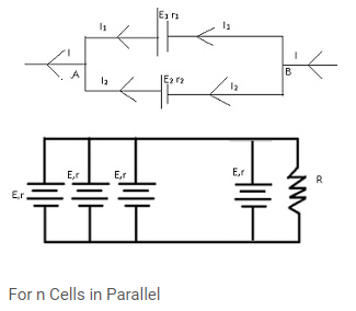
Cells in Parallel

- Potential difference (first cell) =E1; potential difference (second cell) =E2.
- Internal resistance (first cell) =r1; Internal resistance (second cell) =r2.
- As current is flowing through the cell internal resistance is offered to the cell.
- Equation for potential difference E1(first cell):-
- Potential difference between 2 points A and B.
- Therefore V =E1 –I1r1(for first cell)
- (Current I gets divided into 2 parts I1 and I2; I1 acrossE1).
- I1 =(E1-V)/r1 (Equation(i))
- Equation for potential difference E2(second cell):-
- V=E2 –I2r2 (current I2flows across E2).
- I2 =(E2-V)/r2 (Equation(ii))
- Also I=I1 + I2
- Therefore using (i) and (ii) I=(E1-V)/r1 +(E2-V)/r2 =>((E1/r1)+(E2/r2) –(V(1/r1)-(1/r2))
- => V=((I)/(1/r1)+(1/r2)) +((E1/r1) +(E2/r2)/(1/r1)+(1/r2))
- V=I((r1r2)/r1 + r2)) +(E1r1 +E2r2)/(r1 + r2) (Equation(iii))
- Instead of 2 cells if we consider only 1 cell i.e. Eequivalent= (E1and E2) and resistance=requivalent= (r1 andr2).
- Therefore V=Eequivalent – Irequivalent (equation(iv))
- From Equation (iii),V=(I)/((1/r1)) +(E1/r1)+(E2r2) /((1/r1)+(1/r1))(Equation(v))
- After simplifying and Comparing (v) and (iv),requivalent =( r1 + r2)/( r1 + r2), Eequivalent =( E1 r1 + E2 r2)/( r1 + r2)
- Case: –
- n cells are connected in a parallel combination across an external resistance R.
- Internal Emf of each cell = E; internal resistance =r;
- Using Eequivalent =( E1 r1 + E2 r2)/( r1 + r2) ;Putting r1= r2=r ,E1=E2=E; Eequivalent =((Er)/n)
- Total resistance=R +requivalent = (r/n)
- Current through R, I=(Effective Emf)/(total resistance)=(E)/(R+(r/n)) =(nE)/(nR+r)
- Case 1: R<<r; I=nE/r
- Case 2:- R>>>r ; I =E/r
- Important Note:-
- Cells are arranged in series to increase the voltage.
- Cells are increased in parallel to increase the current.
Problem:-
Three resistors 2 Ω, 4 Ω and 5 Ω are combined in parallel. What is the totalresistance of the combination?
(b) If the combination is connected to a battery of Emf 20 V and negligible internal resistance, determine the current through each resistor, and the total current drawn from the battery.
Answer:-
(a) There are three resistors of resistances,R1 = 2 Ω, R2 = 4 Ω, and R3 = 5 Ω
They are connected in parallel. Hence, total resistance (R) of the combination is given by,
(1/R) =(1/ R1)+(1/R2)+(1/ R3)
=(1/2)+(1/4)+(1/5)=(10+5+4)/20 =(19/20)
R= (20/19)Ω
Therefore, total resistance of the combination is (20/19)Ω.
(b) Emf of the battery, V = 20 V
Current (I1) flowing through resistor R1 is given by,I1 = (V/R1) = (20/2) =10A
Current (I2) flowing through resistor R2 is given by,I2 = (V/R2) = (20/4) =5A
Current (I3) flowing through resistor R3 is given by,I3 = (V/R3) = (20/5) =4A
Total current, I = I1 + I2 + I3 = 10 + 5 + 4 = 19 A
Therefore, the current through each resister is 10 A, 5 A, and 4 A respectively and thetotal current is 19 A.
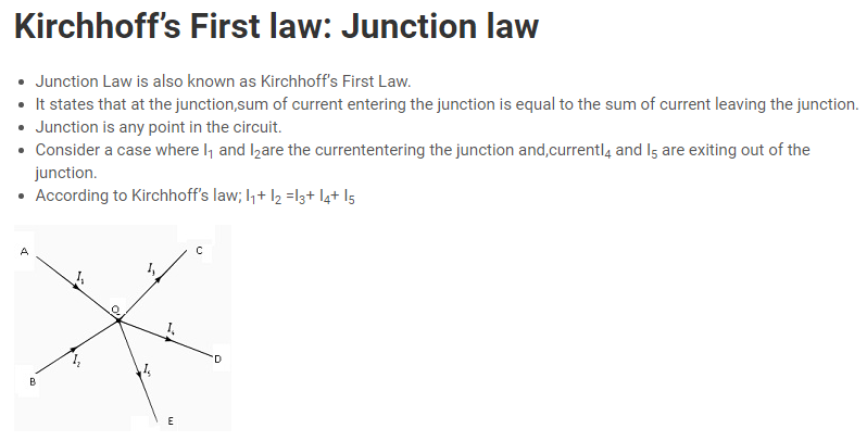
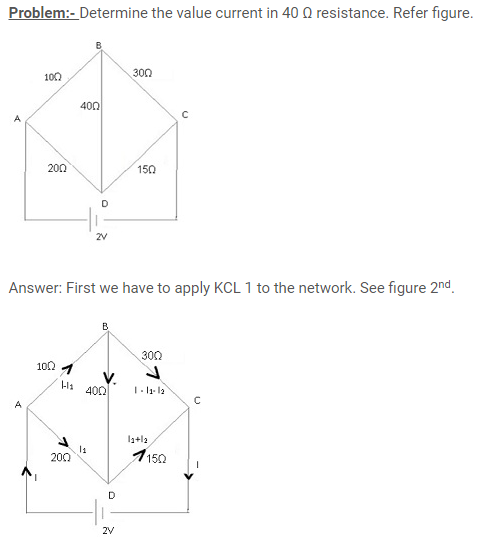
Note that there are three unknown variables (I, I1, I2) and therefore we need to solve three equations simultaneously to find this unknown variable.
Apply KCL to Circuit ABDA
∑ IR = ∑ Emf
(I – I1)*10 + I2*40 – 20I = 0
10*I – 30*I1 +40*I2 = 0 ————————- (1)
Apply KCL to Circuit BCDB
(I – I1 – I2)*30 – (I1+I2)*15 – I2*40 = 0
30*I – 45*I1 – 85*I2 = 0 ————————- (2)
Apply KCL to Circuit ADCEA
I1*20 + (I1+I2)*15 = 2
35*I1 + 15*I2 = 2 —————————– (3)
Now solve these three equations
I = 87/785 A
I1 = 41/785 A
I2 = 9/785 A
So the current in 60 Ohms resistance is 9/785 A from B to D.
Kirchhoff’s Second law: Loop law
- Loop law is also known as Kirchhoff’s Second Law.
- It states that in a closed loop,algebraic sum of Emfsis equal to the algebraic sum of product of resistances and respective currents flowing through them.
- Consider a simple circuit havingEmfs = E1 and E2; R1 and R2 =resistances; current =I1 and I2.
- Then according to this law : E1+E2=I1R1+ I2R2
- For example:-
- Consider given figure,let Emfs be E1 and E2 internal resistances be R1, R2 and R3.
- Steps to use Kirchhoff’s law:-
- Choose the loop to apply Kirchhoff’s law.
- Assume any direction.
- Emf is +ive if assumed direction leaving +ive terminal of battery.
- IR is +ive if the current in the assumed direction.
- Consider closed loop ABCDFA, using the assumptions;
- E2=+R2I3 +R3I2 ;where I3=current flowing through R3
- Closed loop FCDEF, +E1= +I1R1 + I3R2
- Closed loop ABDEA, -E1 + E2 = -I1R1 +I2R3
- If the direction of current is taken opposite then
- Closed loop ABCDFA ;- -E2=-R2I3-R3I2
- FCDEF; -E1= -I1R1 – I3R2
- ABDEA; +E1 – E2 = +I1R1 -I2R3
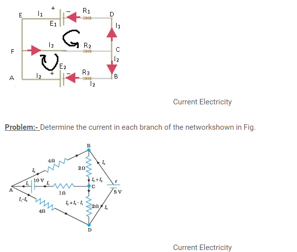
Answer:- Each branch of the network is assigned an unknown currentto be determined by the application of Kirchhoff’s rules. To reducethe number of unknowns at the outset, the first rule of Kirchhoff isused at every junction to assign the unknown current in each branch.
We then have three unknowns I1, I2 and I3 which can be found byapplying the second rule of Kirchhoff to three different closed loops.
Kirchhoff’s second rule for the closed loop ADCA gives,
10 – 4(I1– I2) + 2(I2 + I3 – I1) – I1 = 0 that is, 7I1– 6I2 – 2I3 = 10 (a)
For the closed loop ABCA, we get
10 – 4I2– 2 (I2 + I3) – I1 = 0that is, I1 + 6I2 + 2I3 =10 (b)
For the closed loop BCDEB, we get
5 – 2 (I2 + I3) – 2 (I2 + I3 – I1) = 0that is, 2I1 – 4I2 – 4I3 = –5 (c)
Equations (a, b, c) are three simultaneous equations in threeunknowns. These can be solved by the usual method to give;
I1 = 2.5A, I2 = (5/8) A, I3 = (15/8) A
The currents in the various branches of the network are
AB:(5/8) A, CA: (5/2) A, DEB: (15/8) A
AD: (15/8) A, CD: 0 A, BC: (5/2) A
It is easily verified that Kirchhoff’s second rule applied to theremaining closed loops does not provide any additional independentequation, that is, the above values of currents satisfy the secondrule for every closed loop of the network. For example, the total voltagedrops over the closed loop BADEB: (5V) + ((5/8) x 4) V – ((15/8) x 4) V equal to zero, as required by Kirchhoff’s second rule.
Problem:- Determine the current in each branch of the network shown in given fig?
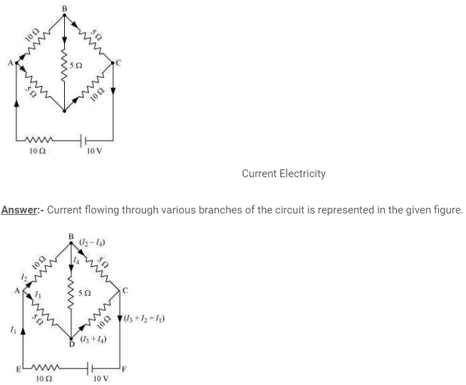
I1 = Current flowing through the outer circuit
I2 = Current flowing through branch AB
I3 = Current flowing through branch AD
I2 − I4 = Current flowing through branch BC
I3 + I4 = Current flowing through branch CD
I4 = Current flowing through branch BD
By Loop law:-
For the closed circuit ABDA, potential is zero i.e.
10I2 + 5I4 − 5I3 = 0
2I2 + I4 −I3 = 0
I3 = 2I2 + I4 … (1)
For the closed circuit BCDB, potential is zero i.e.
5(I2 − I4) − 10(I3 + I4) − 5I4 = 0
5I2 + 5I4 − 10I3 − 10I4 − 5I4 = 0
5I2 − 10I3 − 20I4 = 0
I2 = 2I3 + 4I4 … (2)
For the closed circuit ABCFEA, potential is zero i.e.
−10 + 10 (I1) + 10(I2) + 5(I2 − I4) = 0
10 = 15I2 + 10I1 − 5I4
3I2 + 2I1 − I4 = 2 … (3)
From equations (1) and (2), we obtain
I3 = 2(2I3 + 4I4) + I4
I3 = 4I3 + 8I4 + I4
− 3I3 = 9I4
− 3I4 = + I3 … (4)
Putting equation (4) in equation (1), we obtain
I3 = 2I2 + I4
− 4I4 = 2I2
I2 = − 2I4 … (5)
It is evident from the given figure that,
I1 = I3 + I2 … (6)
Putting equation (6) in equation (1), we obtain
3I2 +2(I3 + I2) − I4 = 2
5I2 + 2I3 − I4 = 2 … (7)
Putting equations (4) and (5) in equation (7), we obtain
5(−2 I4) + 2(− 3 I4) − I4 = 2
− 10I4 − 6I4 − I4 = 2
17I4 = − 2
I4 = – (2/17)
Equation (4) reduces to
I3 = − 3(I4)
=-3(-2/17) = (6/17) A
I2=-2(I4)
=-2(-2/17) = (4/17) A
I2 – I4 = (4/17) – (-2/17) = (6/17) A
I3+I4 = (6/17) + (-2/17) = (4/17) A
I1 =I3 + I2 = (6/17) + (4/17) = (10/17) A
Therefore, current in branch AB= (4/17) A
In branch BC = (6/17) A
In branch CD = (4/17) A
In branch AD= (6/17) A
In branch BD = (-2/17) A
Total Current =(4/17) +(6/17)+(-4/17)+(6/17)+(-2/17)=(10/17) A
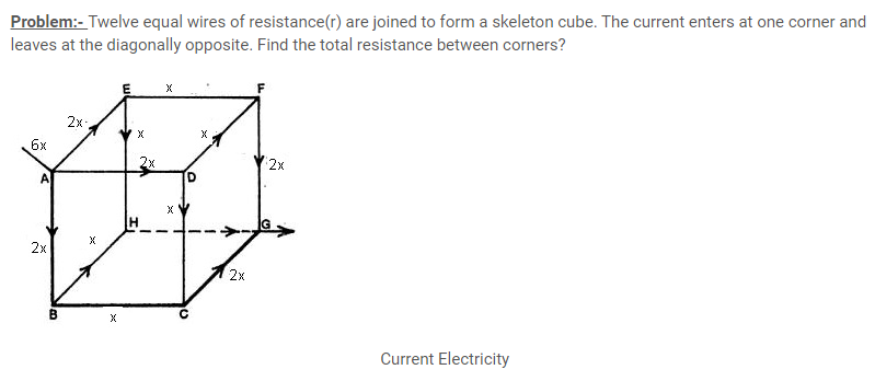
Answer:- Here, 12 resistances are arranged such that they form a cube.Now each of the 12 wires represents a resistor of value ‘R’.We need to calculate the resistance across face diagonal corners.
Now,let us assume that we have attached a voltage source across(or Emf V) the ends of points A and B and then the current starts to flow in the network.We have also assumed that, a current of ‘6x’ flows through point A and thus splits up equally into three parts of current ‘2x’ each(as resistance is same in each arm) and each ‘2x’ current further splits into two equal parts of current ‘x’ each. We need to calculate the equivalence resistance(r) across the terminal AG which is the corner diagonal of the cube.
Applying Kirchhoff’s law in loop ABCGA, we get
V=2xR+xR+2xrR
So,V=5xR (1)
Now from also from Ohm’s law
V=r.6x (2)
Here,’V’ is the potential difference applied,’6x’is the total current supplied and ‘r’ is the net resistance of the circuit.So, by putting the value of V from (1) in(2),we get
5xR=r.6x
Therefore r=(5/6)R
Wheatstone bridge
- Wheatstone bridge is a special arrangement of resistors as shown in the figure.
- There are 4 resistances R1,R2,R3and R4 arranged in such a manner thatthere is a galvanometer placed between the points B and D.
- The arm BD is known as galvanometer arm. AC is known as battery arm.
- And circuit is connected to the battery across the pair of diagonally opposite points A and C.
- According to Wheatstone bridge principle:-
- If (R1/R2)=(R3/R4), then Bridge is said to be balanced.
- If the bridge is balanced there is no current flowing through the galvanometer arm.
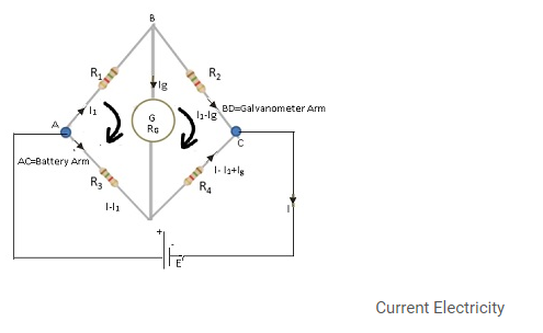
Mathematically:-
- Assume current across the galvanometer arm Ig =0;
- To prove:-(R1/R2) = (R3/R4)
- Applying loop law to the loop ABDA,
- There is no Emf, therefore,
- 0= I1R1 – (I-I1)R3 + IgRG equation (i) where RG=resistance of galvanometer.
- Applying loop Law to the loop BCDB,
- No Emf, 0=(I1-Ig)R2 –(I-I1+Ig)R4 +IgRGequation(ii)
- Putting Ig=0 in equation(i) and (ii)
- I1R1 – (I-I1) R3 = 0 => I1R1 = (I-I1) R3 equation (iii)
- I1R2 –(I-I1)R4 =0 => I1R2 =(I-I1) equation(iv)
- Dividing equation(iii) with (iv)
- (R1/R2) =(R3/R4) Hence proved.
Meter Bridge
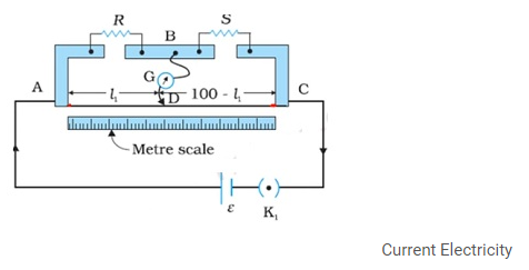
- Meter Bridgeconsists of a wire whose length is 1m.That is why known as Meter Bridge.
- Construction:-
- The lengths of the wire are stretched between two metallic strips.
- There is a one more metallic strip presentbetween the metallic stripsso that resistances can be placed between them.
- Value of one resistance is known and value of another resistance is unknown.
- There is a jockey(object capable of sliding over the wire) whose one end is connected to galvanometer and other end to metal strip.
- There is a metre scale held parallel to this wire of length 1m.
- As jockey moves over the wire there will be one point where galvanometer shows 0 deflection.
- The length AD= l1 and DC = (100-l1).
- Resistance of AD=Rcml1, where Rcm is the resistance of the wire per unit centimetre.
- Resistance of DC=Rcm (100-l1).
- The four arms AB, BC, DA and CD [with resistances R, S, Rcm l1 and Rcm (100-l1)] form a Wheatstone bridge with AC as the battery arm and BD the galvanometer arm.
- When there is no deflection in the galvanometer then (R/S) =(Rcml1)/Rcm(100-l1).
- Therefore S=(Rcml1)/(Rcm(100-l1)).=>S=((100-l1)/(l1))R
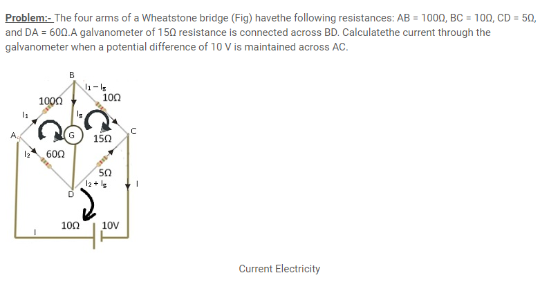
Answer:- Considering the mesh BADB, we have
100I1 + 15Ig – 60I2 = 0
or 20I1 + 3Ig – 12I2= 0 (a)
Considering the mesh BCDB, we have
10 (I1 – Ig) – 15Ig – 5 (I2 + Ig) = 0
10I1 – 30Ig –5I2 = 0
2I1 – 6Ig – I2 = 0 (b)
Considering the mesh ADCEA,
60I2 + 5 (I2 + Ig) = 10
65I2 + 5Ig = 10
13I2 + Ig = 2 (c)
Multiplying Eq. () by 10
20I1 – 60Ig – 10I2 = 0 (d)
Fromequations (d) and (a) we have
63Ig – 2I2 = 0
I2 = 31.5Ig [(e)]
Substituting the value of I2 into Eq. (c), we get
13 (31.5Ig) + Ig = 2
410.5 Ig = 2
Ig = 4.87 mA.
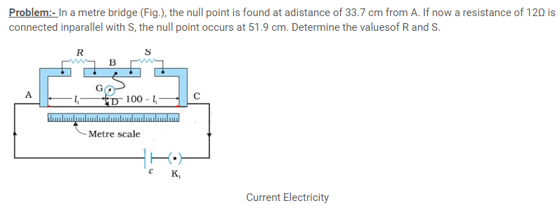
Answer: – From the first balance point, we get
(R/S) = (33.7)/ (66.3) = (3.87) (i)
After S is connected in parallel with a resistance of 12Ω, the resistanceacross the gap changes from S to Seq, where
Seq= (12S)/(S+12) and hence the new balance condition now gives
(51.9)/ (48.1) =(R/ Seq) =R(S+12)/ (12S)
Substituting the value of (R/S) from Eq. (i), we get
(51.9)/ (48.1) = ((S+12)/12) x (33.7)/ (66.3)which gives
S = 13.5Ω. Using the value of (R/S) above, we get
R = 6.86 Ω
Potentiometer
- Potentiometer consists of long wire with uniform cross-section.
- Instead of long wire small pieces of wire is taken and each of those pieces are fixed parallel to each other on a platform.
- Wires are connected by a copper strip. As there are 6 pieces of wire therefore the length of the wire =6m.
- There is a driving circuit which consists of battery, key and rheostat.
- This is the circuit which will provide the current, and this current flow through this longwire.
- Galvanometer
- One end of galvanometer is connected to the point AB on the circuit with the help of jockey, and other end is left free.
- Terminals of potentiometer(End points)
- These are the points between which the potential difference needs to be measured.
- One endpoint = free end of the galvanometer and other endpoint = the one end of wire A of the circuit.
- End A is at higher potential and end B is at lower potential.
- Graduated scale for measurement.
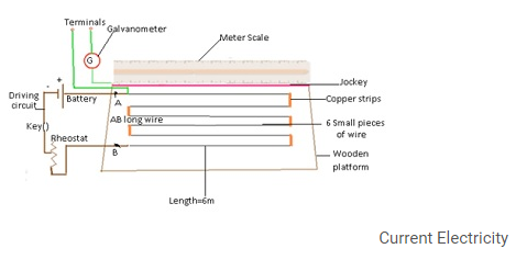
Working:-
- To find out potential difference between 2 points(a and b) of the circuit.
- Point A is connected to (a)and point C is connected to (b).
- Assume all the connecting wires have 0 resistances.
- Potential at point ‘a’= Potential at point ‘A’.
- Similarly potential at ‘b’=Potential at some point before B.
- While Sliding the jockey there will be a point where galvanometer shows deflection equal to 0.Let that point be P.
- Therefore, potential at point ‘b’=potential at point ‘P’.
- Let AB=L(length) and AP=l.At L=value of deflection is 0.
- Potential due to driving circuit=V0=potential between A and B.
- Potential gradient(ρ)=(potential between A and B)/(length of AB) =(V0/L)
- Potential between A and P (V0) = Potential between ‘a’ and ‘b’ (V).
- =(ρ x l)=(V0/L)xl Equation (i)
- To determine V0:-
- Replace ‘a’ and ‘b’ with a cell of known Emf(E)= V0(l0)/L=> V0=(EL)/( l0)
- Where l0 =deflection in galvanometer is 0.
- Using (i) => V=V0(l/L)=(EL)/ ( l0)
- Therefore V=(El)/(l0)
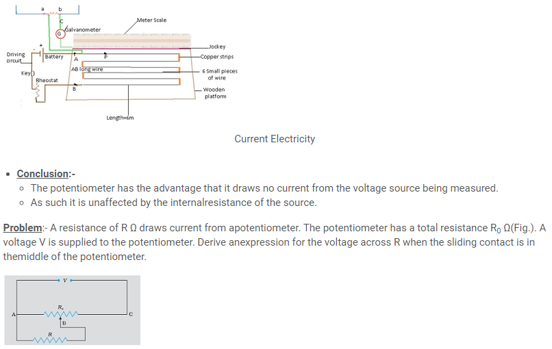
Answer: – While the slide is in the middle of the potentiometer onlyhalf of its resistance (R0/2) will be between the points A and B. Hence,the total resistance between A and B, say, R1, will be given by thefollowing expression:
(1/R1)= (1/R) + (1/R0/2)
R1 =(R0R)/ (R0+2R)
The total resistance between A and C will be sum of resistance betweenA and B and B and C, i.e., (R1 + R0/2)
∴The current flowing through the potentiometer will be
I= (V)/(R1 + R0/2)
The voltage V1 taken from the potentiometer will be the product ofcurrent I and resistance R1,
V1 = I R1 = (2V)/ (2R1R0) x R1
Substituting for R1, we have a
V1= (2V)/ ((2(R0xR)/ (R0+2R)) +R0) x ((R0xR)/ (R0+2R))
V1= (2VR)/ (2R+R0+2R)
Or V1= (2VR)/ (R0+4R)
Problem:- In a potentiometer arrangement, a cell of Emf 1.25V gives a balance point at 35.0 cm length of the wire. If a cell is replaced by another cell and the balance point shifts to 63.0cm,what is the Emf of the second cell?
Answer:- Emf of the cell, E1=1.25V
Balance point of the potentiometer, I1=35cm
The cell is replaced by another cell of Emf E2.
New balance point of the potentiometer, I2=63cm
The balance condition id given by the relation,
(E1/E2) = (I1/I2)
E2 =E1 x (I2/I1)
=1.25x(63/35)
=2.25V.
Therefore, Emf of the second cell is 2.25 V.

Answer:-
Resistance of the standard resistor, R = 10.0
Balance point for this resistance, l1 = 58.3 cm
Current in the potentiometer wire = i
Hence, potential drop across R, E1 = iR
Resistance of the unknown resistor = X
Balance point for this resistor, l2 = 68.5 cm
Hence, potential drop across X, E2 = iX
The relation connecting Emf and balance point is,
(E1/ E2) = (l1/ l2)
(iR) / (iX) = (l1/ l2)
X= (l1/ l2) x R
= (68.5/58.3) x10
=11.749Ω
Therefore, the value of the unknown resistance, X, is 11.75 Ω.
If we fail to find a balance point with the given cell of Emf, E, then the potential drop across Rand X must be reduced by putting a resistance in series with it. Only if the potential drop across Ror X is smaller than the potential drop across the potentiometer wire AB, a balance point is obtained.
CBSE Class 12 Physics Electric Charge field Notes (Chapter-1)
CBSE Class 12 Physics Electrostatic Potential and Capacitance Notes (Chapter-2)
Go to Next page for important question
Mohd. Sharif Qualification: B.Tech (Mechanical Engineering) [Founder of Wisdom Academy] [Aim Foundation & Free-Education.In] [Engineer By Profession | Teacher By Choice] [Blogger, YouTube Creator]


