Welcome to our informative blog, where we delve into the fundamental concepts of automobile engineering, elucidate key terms, provide definitions, and present interview-related questions organized by topics. Automobile Engineering is a dynamic field that delves into the intricate design, manufacturing, and research & development of vehicles like cars, trucks, buses, and motorcycles.
Specially in India, Automobile industry is changing every day as the new technology arriving and creating a huge career prospective in India. So as a employee or student, we have to keep our self updated to explore new opportunity in new technology.
There are lots of job opportunity for automobile engineer in production plants, automobile manufacturing industries, service stations of automobile companies, motor vehicle departments of control, transport companies, insurance company experts, and state transport corporations, etc. the students are taught to be experts in CAD (Computer-Aided Design), CAM, ERP and therefore one can easily join designing companies as designers of automobile.
Topics :
- What is Automobile Engineering
- Working of Car
- Layout of Car
- Components of Automobile Engine
- Types of Brake
- Clutch Introduction
- Differential Introduction
- Need of Differential
- Gear Introduction
- Suspension System
- Transmission Systems
What is Automobile Engineering
Automobile Engineering is a branch of engineering which deals with designing, manufacturing and operating automobiles. It is a segment of vehicle engineering which deals with motorcycles, buses, trucks, etc. It includes mechanical, electrical, electronic, software and safety elements.
ऑटोमोबाइल इंजीनियरिंग इंजीनियरिंग की एक शाखा है जो ऑटोमोबाइल के डिजाइन, निर्माण और संचालन से संबंधित है। यह वाहन इंजीनियरिंग का एक खंड है जो मोटरसाइकिल, बसों, ट्रकों आदि से संबंधित है। इसमें मैकेनिकल, इलेक्ट्रिकल, इलेक्ट्रॉनिक, सॉफ्टवेयर और सुरक्षा तत्व शामिल हैं।
Skills Required to become Automobile Engineer :
- Artistic
- Creative
- Technical knowledge
- Effective planner
- Precision
- Meticulous
- Systematic
- Punctual
- Team worker
आवश्यक योग्यता:
कलात्मक , रचनात्मक , तकनीकी ज्ञान , प्रभावी योजनाकार , परिशुद्धता , सावधानीपूर्वक , व्यवस्थित , समयनिष्ठ , टीम कार्यकर्ता
The work of an automotive engineer breaks down into three categories:
Design
Designing new products and improving existing ones
Research and Development
Finding solutions to engineering problems
Production
Planning and designing new production processes
ऑटोमोटिव इंजीनियर का काम तीन श्रेणियों में विभाजित होता है:
डिज़ाइन : नए उत्पादों को डिजाइन करना और मौजूदा में सुधार करना
अनुसंधान और विकास : इंजीनियरिंग समस्याओं का समाधान खोजना
उत्पादन : नई उत्पादन प्रक्रियाओं की योजना बनाना और डिजाइन करना
Employment Opportunities:
Automobile engineering is a huge industry. There are a great number of employment opportunities in the following fields:
- Private national and multinational automobile companies
- Service stations
- Private transport companies
- Defence services
- Self-employment by setting up automobile garage or maintenance workshops
रोजगार के अवसर:
ऑटोमोबाइल इंजीनियरिंग एक बहुत बड़ा उद्योग है। निम्नलिखित क्षेत्रों में रोजगार के अपार अवसर हैं:
- निजी राष्ट्रीय और बहुराष्ट्रीय ऑटोमोबाइल कंपनियां
- सर्विस स्टेशन
- निजी परिवहन कंपनियां
- रक्षा सेवाएं
- ऑटोमोबाइल गैरेज या रखरखाव कार्यशालाएं स्थापित करके स्वरोजगार
1 What is Automobile Engineering ?
2 What are Career Options For Automobile Engineer ?
3 What are skilled required to become Automobile Engineer.
4 Define the work category for automobile engineer.
Let’s Understand How a Car Works (Working of a Car)
When a driver turns a key in the ignition:
- 1. The car battery powers up & sending power to the starter motor, which turns the crankshaft, due to which Gets the pistons moving
- 2. With the pistons moving the engine fires up and ticks over
- 3. A fan draws air into the engine via an air filter
- 4. The air filter removes dirt and grit from the air
- 5. The cleaned air is drawn into a chamber where fuel (petrol or diesel) is added
- 6. This fuel-air mix (a vaporised gas) is stored in the chamber
- 7. The driver presses the accelerator pedal
- 8. The throttle valve is opened
- 9. The gas-air mix passes through an intake manifold and is distributed, through intake valves, into the cylinders. The camshaft controls the opening and closing of the valves.
- 10. The distributor makes the spark plugs spark, which ignites the fuel-air mix. The resulting explosion forces a piston to move down which in turn causes the crankshaft to rotate.
Q. Explain the complete function of how a car works ?
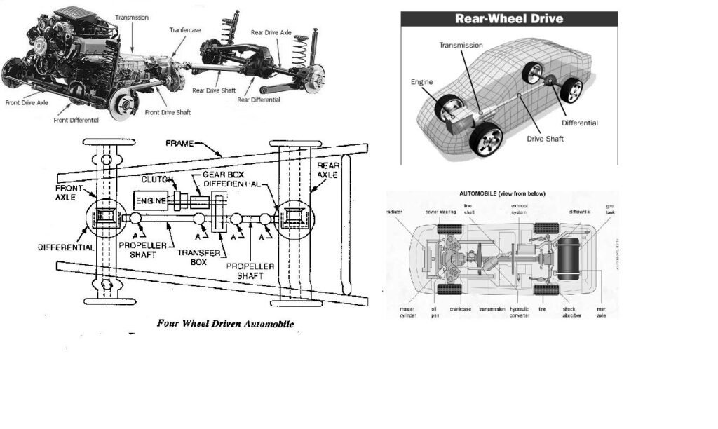
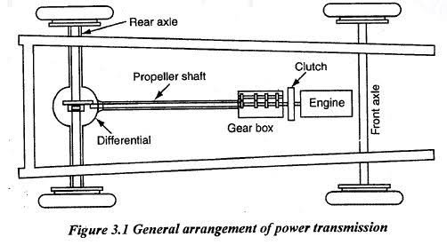
Layout of Car
Layout of the car indicate the location of engine, clutch, gear box, differential, front and rear wheel in the vehicle.
The layout of the car mainly distribute in two categories
- Front wheel drive
- Rear wheel drive
Q1. Draw a car layout ?
Q2. What are the functions of a frame?
- To support the chassis components and the body.
- To withstand static and dynamic loads without undue deflection or distortion.
- For carry the load of the passengers or goods carried in the body.
Q3. List out the various materials used in the construction of chassis frames.
- Low Carbon Steel – 0.18 or 0.20 % carbon content
- High Carbon Steel – 0.25 % carbon content
- Alloy Steel – With alloying elements like Ni & Cr
Components of Automobile Engine & Terms

1. Cylinder Block
This is a cast structure with cylindrical holes bored to guide and support the piston and to harness the working gases. It also provides a jacket to contain a liquid coolant.
2. Piston
This is a pressure-tight cylindrical plunger which is subjected to the expanding gas pressure. Its function is to convert the gas pressure from combustion into a concentrated driving thrust along the connecting rod. It must therefore also act as a guide for the small end of the connecting rod.
3. Piston Rings
These are circular rings which seal the gaps made between the piston and the cylinder, their object being to prevent gas escaping and to control the amount of lubricant which is allowed to reach the the top of the cylinder.
4. Gudgeon-pin
These pin transfers the thrust from the piston to the connecting rod small end while permitting the rod to rock to and fro as the crankshaft rotates.
5. Connecting rod
This acts as both a strut and a tie link-rod. It transmits the linear pressure impulses acting on the piston to the crankshaft big end journal, where they are converted into turning-effort.
6. Crankshaft
A simple crankshaft consists of a circular sectioned shaft which is bent or cranked to form two perpendicular crank arms and an offset big-end journal. The crankshaft is indirectly linked by the connecting rod to the piston – this enables the straight-line motion of the piston to be transformed into a rotary motion a t the crankshaft about the main journal axis.
It is essentially the backbone of the internal combustion engine. The crankshaft is responsible for the proper operation of the engine and converting a linear motion to a rotational motion. Crankshafts should have very high fatigue strength and wear resistance to ensure long service life.
7. Crankshaft Journals

A journal is the part of a shaft that rotates inside a bearing. As can be seen above, there are two types of journal on a crankshaft – the main bearing journals form the axis of rotation for the crankshaft, and the connecting rod journals are secured to the ends of the connecting rods, which run up to the pistons.
8. Small end
The end at which the connecting rod is attached to the face of the piston pin is known as the small end of the connecting rod.
9. Main ends
This refers to the rubbing pairs formed between the crankshaft main journals and their respective plain bearings mounted in the crankcase.
10. Line of stroke
The centre path the piston is forced to follow due the constraints of the cylinder is known as the line of stroke.
11. Inner and outer dead centres
When the crankarm and the connecting-rod are aligned along the line of stroke, the piston will be in either one of its two extreme positions. If the piston is at its closest position to the cylinder head, the crank and piston are said to be at inner dead centre (IDC) or top dead centre (TDC). With the piston at its furthest position from the cylinder head, the crank and piston are said to be at outer dead center (ODC) or bottome dead centre (BDC). These reference points are of considerable importance fo r valve-to-crankshaft timing and for either ignition or injection setting.
12. Clearance Volume
The space between the cylinder head and the piston crown at TDC is known as the clearance volume of the combustion-chamber space.
13. Crank Throw
The distance from the centre of the crankshaft main journal to the centre of the big end journal is is known as the crank throw. This radial length influences the piston can apply in rotating the crankshaft.
14. Piston stroke
The piston movement from IDC to ODC is known as the piston stroke and corresponds to the crankshaft rotating half a revolution or 180. It is also equal to twice the crank-throw.
i.e. L = 2R
Where L = Piston stroke and R = Crank-Throw.
Thus a long or short stroke will enable a large or small turning-effort to be applied to the crankshaft respectively.
15. Cylinder bore
The cylinder block is initially cast with sand cores occupying the cylinder spaces. After the sand cores have been removed, the rough holes are machined with a single-point cutting tool attached radially at the end of a rotating bar. The removal of the unwanted metal in the hole is commonly known as boring the cylinder to size. Thus the finished cylindrical hole is known as the cylinder bore, and its internal diameter simply as the bore or bore size.
Q. What are the two types of cylinder liners?
• Dry liners
• Wet liners
Q. What are the functions of piston rings?
To provide a gas tight seal between the piston and cylinder liner to prevent the escape of gases from top side of the piston to the underside.
Q. What are the two types of piston rings?
• Compression rings
• Oil rings
Q. What is the function of piston, connecting rod, crank shaft and cylinder head?
• 1. Piston – The piston assembly transfers the force from the power stroke to the crankshaft
• 2. Connecting rod – converts reciprocating motion of piston into rotary motion of crankshaft
• 3. Cylinder head – it acts as a top cover to the cylinder block. The valves are placed in the cylinder head in an overhead valve engine.
SPARK PLUG
Spark plug is a device used to produce electric spark to ignite the compressed air fuel mixture inside the cylinder. The spark plug is screwed in the top of the cylinder so that it electrode project in the combustion chamber.


A spark plug consist of mainly three parts:
1. Center electrode or insulated electrode.
2. Ground electrode or outer electrode.
3. Insulation separating the two electrodes.
The upper end of the centre electrode is connected to the spark plug terminal, where cable from the ignition coil is connected. It is surrounded by insulator. The lower half portion of the insulator is fastened with a metal shell. The lower portion of the shell has a short electrode attached to one side and bent in towards the centre electrode, so that there is a gap between the two electrodes. The two electrodes are thus separated by the insulator. The sealing gaskets are provided between the insulator and the shell to prevent the escape of gas under various temperature and pressure conditions. The lower part of the shell has screw threads and the upper part is made in hexagonal shape like a nut, so that the spark plug may be screwed in or unscrewed from the cylinder head.
Cleaning the Spark Plug
Due to the combustion of fuel in the cylinder, carbon particles deposit on and around the electrode which not only reduce the plug gap but also prevent the spark to occur. If the spark is still occurring, it is too weak that it cannot ignite the fuel. Hence the spark plug is to be cleaned. Carbon particles can deposit due to any reason like, nature of fuel, mixture strength, lubricating oil, etc. The spark plug can be cleaned by a sand paper.
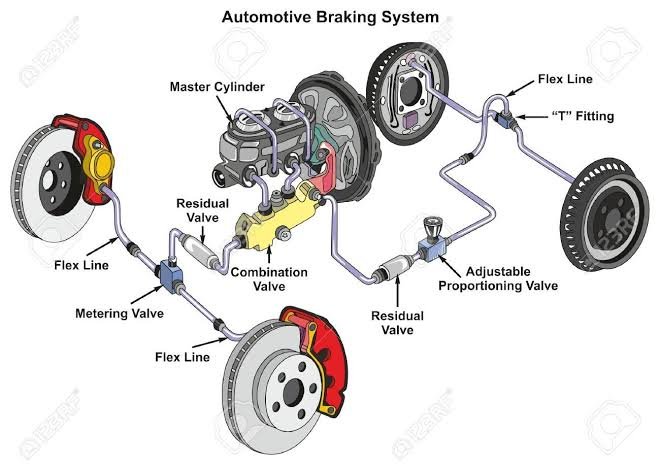
Brakes and Its types of Brakes
Brake Introduction :-
A brake is a mechanical device which inhibits motion. Its opposite component is a clutch. Brake pedal slows a car to a stop.When you depress your brake pedal, your car transmits the force from your foot to its brakes through a fluid. Since the actual brakes require a much greater force than you could apply with your leg, your car must also multiply the force of your foot.
The brakes transmit the force to the tires using friction, and the tires transmit that force to the road using friction also.
Almost all wheeled vehicles have a brake of some sort. Even baggage carts and shopping carts may have them for use on a moving ramp. Most fixed-wing aircraft are fitted with wheel brakes on the undercarriage. Some aircraft also feature air brakes designed to reduce their speed in flight. Friction brakes on automobiles store braking heat in the drum brake or disc brake while braking then conduct it to the air gradually. When traveling downhill some vehicles can use their engines to brake.

Types of Brakes
Brakes may be broadly described as using friction, pumping, or electromagnetic. One brake may use several principles: for example, a pump may pass fluid through an orifice to create friction:
1. Frictional Brake
2. Pumping Brake
3. Electromagnetic Brake
4. Hydraulic Brake
5. Air Brake
6. Anti-Braking System(ABS)
Clutch Introduction
A Clutch is a machine member used to connect the driving shaft to a driven shaft, so that the driven shaft may be started or stopped at will, without stopping the driving shaft. A clutch thus provides an interruptible connection between two rotating shafts. Clutches allow a high inertia load to be stated with a small power.
Function of Clutch:
Clutches are used whenever the ability to limit the transmission of power or motion needs to be controlled either in amount or over time (e.g. electric screwdrivers limit how much torque is transmitted through use of a clutch; clutches control whether automobiles transmit engine power to the wheels).
In the simplest application clutches are employed in devices which have two rotating shafts. Here these devices one shaft is typically attached to a motor or other power unit (the driving member) while the other shaft (the driven member) provides output power for work to be done. In a drill for instance, one shaft is driven by a motor and the other drives a drill chuck. The clutch connects the two shafts so that they may be locked together and spin at the same speed (engaged), locked together but spinning at different speeds (slipping), or unlocked and spinning at different speeds (disengaged).
A popularly known application of clutch is in automotive vehicles where it is used to connect the engine and the gear box. Here the clutch enables to crank and start the engine disengaging the transmission Disengage the transmission and change the gear to alter the torque on the wheels. Clutches are also used extensively in production machinery of all types.

When your foot is off the pedal, the springs push the pressure plate against the clutch disc, which in turn presses against the flywheel. This locks the engine to the transmission input shaft, causing them to spin at the same speed.
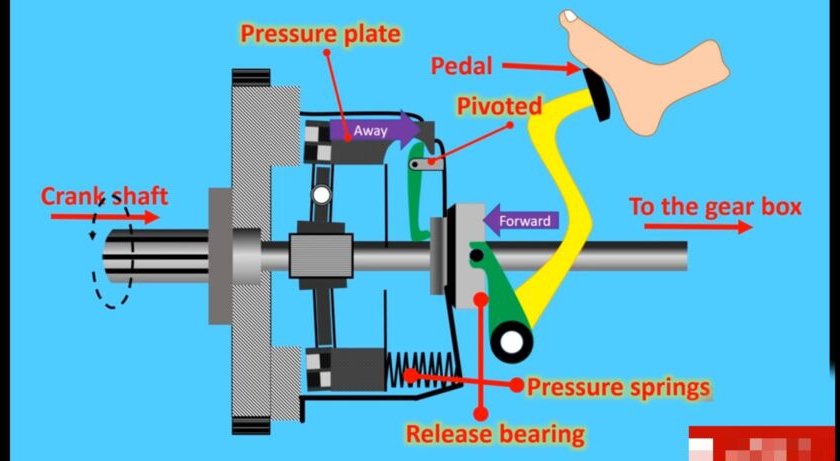
Clutch for a drive shaft:
The clutch disc (centre) spins with the flywheel (left). To disengage, the lever is pulled (black arrow), causing a white pressure plate (right) to disengage the green clutch disc from turning the drive shaft, which turns within the thrust-bearing ring of the lever. Never will all 3 rings connect, with no gaps.
In a car’s clutch, a flywheel connects to the engine, and a clutch plate connects to the transmission.
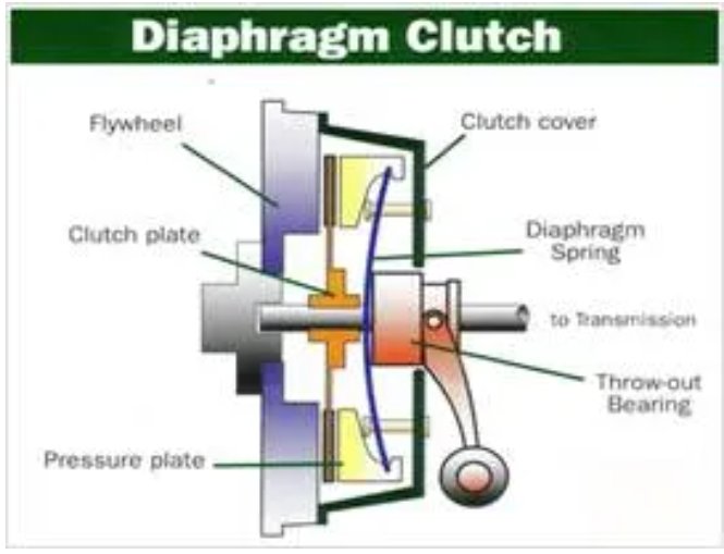
The amount of force the clutch can hold depends on the friction between the clutch plate and the flywheel, and how much force the spring puts on the pressure plate. When the clutch pedal is pressed, a cable or hydraulic piston pushes on the release fork, which presses the throw-out bearing against the middle of the diaphragm spring. As the middle of the diaphragm spring is pushed in, a series of pins near the outside of the spring causes the spring to pull the pressure plate away from the clutch disc (see below). This releases the clutch from the spinning engine.


Differential
As part of the front and/or rear axle assembly, the differential plays an integral role in how your car makes turns. The differential is designed to drive a pair of wheels while allowing them to rotate at different speeds. This function provides proportional RPMs between the left and right wheels. If the inside tire rotates 15 RPM less in a turn than going straight, then, the outside tire will rotate 15 RPM more than going straight.
For example, when your vehicle goes around a corner, the wheel on the outside must travel faster than the wheel on the inside. The differential distributes equal amounts of torque to both wheels. This permits the wheels to react to resistance, or provide traction, to give the wheel more resistance to rotate less. The wheel with less resistance rotates faster.
Some vehicles, such as go-karts, are not equipped with a differential. In this case, both driving wheels are forced to rotate at the same speed, usually on a common axle driven by a simple chain-drive apparatus. Front wheel drive vehicles are designed differently in that the axle and differential assembly is located in the transmission axle assembly or transaxle.

Gears
Gears are used to transfer motion and torque between machine components in mechanical devices. Depending on the design and construction of the gear pair employed, gears can change the direction of movement and/or increase the output speed or torque.
1) Gears are the most common source used for power transmission.
2) They can be applied for two shafts which are-
· Parallel
· Collinear
· Perpendicular & Intersecting
· Perpendicular and Non-intersecting
· Inclined at an arbitrary angle

Suspension System
Suspension is the term given to the system of springs, shock absorbers and linkages that connects a vehicle to its wheels. This systems serve a dual purpose — contributing to the car’s road holding/handling and braking for good active safety and driving pleasure, and keeping vehicle occupants comfortable and reasonably well isolated from road noise, bumps, and vibrations, etc. These goals are generally at odds, so the tuning of suspensions involves finding the right compromise. It is important for the suspension to keep the road wheel in contact with the road surface as much as possible, because all the forces acting on the vehicle do so through the contact patches of the tires. The suspension also protects the vehicle itself and any cargo or luggage from damage and wear.
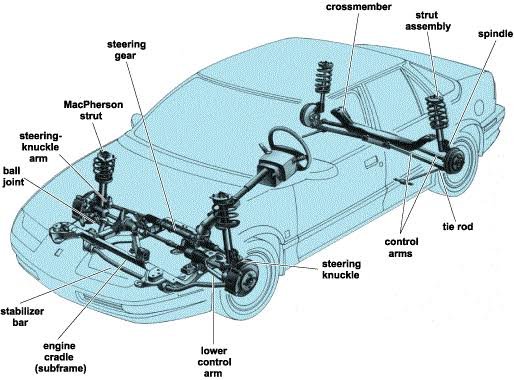

Q. What are two types of vehicle suspensions?
• Rigid axle suspension
• Independent suspension
Transmission
Transmission system in a car helps to transmit mechanical power from the car engine to give kinetic energy to the wheels. It is an interconnected system of gears, shafts, and other electrical gadgets that form a bridge to transfer power and energy from the engine to the wheels. The complete setup of the system helps to maintain the cruising speed of the car without any disturbance to the car’s performance. The oldest variant of the transmission system in India is the manual transmission that has undergone various modifications and alterations to form the present day automatic transmission.
Function of Transmission
A transmission or gearbox provides speed and torque conversions from a rotating power source to another device using gear ratios. The transmission reduces the higher engine speed to the slower wheel speed, increasing torque in the process. A transmission will have multiple gear ratios (or simply “gears”), with the ability to switch between them as speed varies. This switching may be done manually (by the operator), or automatically. Directional (forward and reverse) control may also be provided.
In motor vehicle applications, the transmission will generally be connected to the crankshaft of the engine. The output of the transmission is transmitted via drive shaft to one or more differentials, which in turn drive the wheels.
Most modern gearboxes are used to increase torque while reducing the speed of a prime mover output shaft (e.g. a motor crankshaft). This means that the output shaft of a gearbox will rotate at slower rate than the input shaft, and this reduction in speed will produce a mechanical advantage, causing an increase in torque.


Q. Why you need a gear box?
When a vehicle is moving on a road, it has to encounter different resistances depending upon the road surface, vehicle speed and road gradient. Hence, wheel torque required at road wheels is different for different operating conditions. To satisfy this requirement, a gearbox is necessary in a vehicle.
Mohd. Sharif Qualification: B.Tech (Mechanical Engineering) [Founder of Wisdom Academy] [Aim Foundation & Free-Education.In] [Engineer By Profession | Teacher By Choice] [Blogger, YouTube Creator]