Download Moving Charge & Magnetism notes , In this post We will Study, Moving Charge & Magnetism Notes & Important Topic for Student to excel in exam. NCERT/CBSE class 12th Physics notes provided by free-education.in (Wisdom Education Academy). Here We are providing all subject wise pdf notes to student for their help to get good marks in exam.
In this post you can Download CBSE 2020-21 Physics PDF notes given below by free-education.in to excel in the exam.
www.free-education.in is a platform where you can get pdf notes from 6th to 12th class notes, General Knowledge post, Engineering post, Career Guidelines , English Speaking Trick , How to crack interview and lots more.
INTRODUCTION ( Moving Charge And Magnetism ):
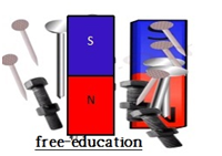
In our childhood, we all might have experienced iron nails getting attracted to a magnet. We have also witnessed or heard current carrying copper wire wound around iron acting as a magnet in a science project. That time all of that seemed magical, although it is all science. It is due to magnetism.
Magnetism is a phenomenon due to which moving charges (or magnets) attract ferromagnetic objects and repel diamagnetic objects.
This diagram below shows that when iron nails are brought closer to a magnet, they get attracted and stick to the magnet
OERSTED EXPERIMENT:
- Oersted in 1820 accidentally found that current and magnetism is closely related
He observed a deflection in a magnetic needle when brought close to a straight wire carrying current
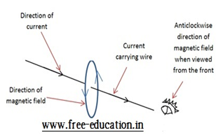
- He then experimented on this phenomenon rigorously to found that the needle deflection was always in the direction of a tangent to a circle drawn with current carrying wire in the center and the wire being perpendicular to the plane of circl
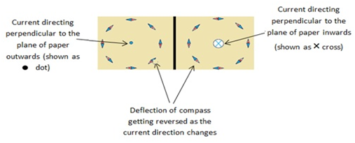
e - When the current direction in the wire was reversed, the deflection in the needle also got reversed
- Also, the deflection increased when a) the current got higher, b) the compass brought closer to the wire, carrying current. The deflection decreased on reducing the current or taking compass farther away from the wire
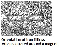
- On scattering iron fillings around the wire, they got oriented in a concentric circles,having wire as their center with current direction perpendicular to the plane of circles
- So, Oersted observed, for the first time that current (charge in motion) creates magnetic field around it.
MAGNETIC FIELD:
- Magnetic field is an effect around a permanent magnet or a moving charge due to which ferromagnetic objects like some metals get attracted, and diamagnetic substances gets repelled, when placed in the magnetic field.
- A charge in motion generates magnetic field, just like a charge at rest generates an electric field
- Magnetic field at a point r is denoted by B(r). It is a vector quantity, just like electric field E(r)
- Magnetic field can change with both distance and time
- Magnetic field due to more than one source can be obtained by vectorial addition of all sources. This is principle of superposition. This characteristic is also similar to electric field.
Lorentz Force and Magnetic Force:
- Leta point charge(q), at any instant, is placed at distance(r) and is advancing with velocity(v) under the influence of electric field(E) and magnetic field(B). Then the net force on the charge is given by:
Fnet = FE + FB = qE + q(vxB)
Here FE = Force on charge due to electric field, FB = Force on charge due to magnetic field
This net force(Fnet) which is the vector sum of forces due to electric and magnetic fields are called as Lorentz Force, named after the scientist Lorentz, who calculated it experimentally.
Force due to magnetic field is: FB = q(vxB) = qvB(sinθ)ȓ
| Hendrik Lorentz |
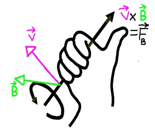
- The direction of force will be given by the cross product of v and B, and is represented by a unit vector ȓ. If we use our palm and curl it into a fist making the thumbs up sign, then if the direction of curling is from v to B, then our thumb will point towards the direction of force as shown in the picture.Here symbols have their usual meaning.
- The force due to magnetic field depends on the charge q, velocity of charge v, the magnetic field B, and the angle θ between v and B.
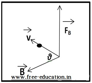
- Keeping the v and B constant, If θ changes, the sine value of it will change, and so does the force. The value of force will be maximum when θ = 90° (v and Bat right angle). The force will be minimum (FB = 0) when θ = 0° or 180°(v and B parallel or anti-parallel to each other respectively)
- For calculating the force due to magnetic field B on a current carrying conductor of length l, and total number of charge moving from one end of conductor to another in time t is q:
F = qvBsinθ = q(l/t)Bsinθ = (q/t)lBsinθ = ilBsinθ
∴FB = ilxB = ilB(sinθ)ȓ
- Here i= current flowing across the said wire, il = current displacement
Numerical Problem:
1) Find the magnitude of magnetic force per unit length on the wire carrying current of 8A, and making angle 30° with the direction of uniform magnetic field of value 0.15T
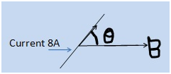
Solution: Given, i = 8A, θ = 30°, B = 0.15T
We know that force on a current carrying wire in external magnetic field is given by:
F = iLBsinθ
So, force per unit length will be:
F/L = iBsinθ =8×0.15×sin30° = 0.6N/m (ans)
2) A wire of length 3cm, and carrying current of 10A, is placed inside a solenoid normal to its axis, having uniform magnetic field of 0.27T. Find the magnitude of force on the wire.
Solution: Given, L = 3cm, i = 10A, θ = 90°(normal), B = 0.27T
So, the force on the wire will be:
F = iLBsinθ = 10×.03×0.27×sin90° = 0.081N (ans)
MOTION OF A CHARGE IN A MAGNETIC FIELD:
- For a charge q moving with velocity v in the presence of magnetic field B, force FB is given by:
FB = q(vxB) = qvB(sinθ)ȓ
- Case-1 (charge moving perpendicular to the magnetic field):When motion of charge v and the magnetic field B are at right angle (90°) to each other, the charge will follow a circular path with forceFB always acting towards the center (Centripetal force) and the velocityvacting tangentially to the circle
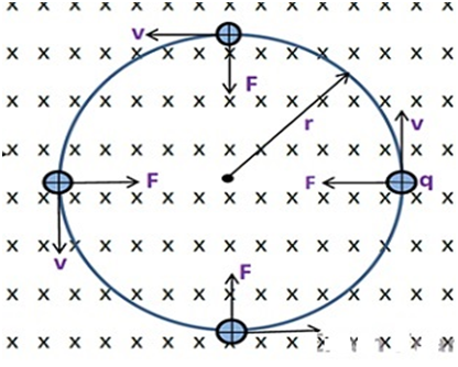
| Direction of magnetic field (B) is normal to the plane of paper and inwards |
- Case-2 (charge moving at an angle θ to the plane of magnetic field):When a charge in motion moves such that the angle between the moving charge and the plane of magnetic field is θ, then the velocity (v) of charge has 2 components, one component along the direction of magnetic field (vcosθ), and the another perpendicular to the magnetic field (vsinθ)
- The component of velocity (vcosθ) along the magnetic field direction, is responsible for the uniform motion of charge along the direction of magnetic field
- The component (vsinθ) perpendicular to the magnetic field will make the charge to follow a circular pathdue to centripetal force FB (just as in case-1)
- These 2 mutually independent motions will cause the charge to move in a helical path as shown below

- To find the radius r of the helix, we can use the centripetal force FC which is provided the force due to magnetic field FB:
FC = FB
mv2/r = qvBsinθ
mv/r = qBsinθ
∴ r = mv/(qBsinθ)
- To find the angular frequency wof the motion of charge:
v = w x r
w = v/r = qB(sinθ)/m
- To find the time T of each revolution:
T = 2π/w = 2πm/(qBsinθ)
- NOTE: The above equations prove that frequency(w) or time period(T) doesn’t depend on the velocity v (or energy) of charge particle
- To find the pitchp of helix, we can use the component of charge velocity along the magnetic field (vcosθ), and the time for each revolution T:
p = v(cosθ) x T = vcosθ x 2πm/(qBsinθ)
∴ p = 2πmv(tanθ)/qB
Numerical Problem:
1) A uniform magnetic field of 6.5G (1G = 10-4T) is maintained. An electron is shot normal to the field with velocity of 4.8×10⁶m/s. Will the motion of electron in the magnetic field be circular, if so, why?
Find the radius and kinetic energy of the electron.
Solution: We already know now that the force of moving charge in an external electric field is:
The direction of force(cross product of v and B) will always be normal to the plane of magnetic field lines, and also normal to the motion of charge (always). And the in the uniform circular motion, centripetal force is also always normal to the motion of object. Hence, the charge will execute a circular motion with force acting as centripetal force.
Radius of circular orbit will be given by: r = mv/(qBsinθ)
m = 9.1×10⁻³¹kg, q = 1.6×10⁻¹⁹C, v = 4.8×10⁶m/s, B = 6.5×10⁻⁴T, θ = 90°
∴r = (9.1×10-31×4.8×106)/(1.6×10-19×6.5×10-4) = 0.042m = 4.2cm (ans)
Kinetic energy of electron will be:
K = ½ mv2 = (9.1×10-31×(4.8×106)2)/2 = 1.05×10⁻¹⁷J (ans)
MOTION IN A COMBINED ELECTRIC AND MAGNETIC FIELD:
- We already know that when a moving charge is acted upon by electric and magnetic fields, the charge experiences a force called Lorentz force, which is a vector sum of forces due to electric and magnetic fields.
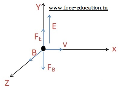
- When the electric field, the magnetic field , and the motion of charge are mutually perpendicular to each other (as shown in the image) , then they are called as crossed fields, and forces due to electric and magnetic fields will act in the opposite directions. So, the Lorentz force F will be:
F = qEî+(qvî x Bk̂) = qEĵ – qVBî = q(E – vB)ĵ
- When the strength of electric and magnetic fields are varied to get the forces due to electric and magnetic field to be equal(FE = FB), then the charge can move in the field without any deflection.
qE = qvB
∴ v = E/B
- This special case shown above is used when we need charged particles of certain velocity (of value E/B) to pass through the crossed fields undeflected, and this phenomenon is called as velocity selector. It was applied by J. Thomson to evaluate the charge to mass ratio in 1897
- This concept of velocity selector is also used in mass spectrometer, where charged objects are distinguished as per their charge to mass ratio.
CYCLOTRON:
- Cyclotron is a device used to accelerate charged bodies to very high velocities (or high kinetic energies) using crossed (or mutually perpendicular) electric and magnetic fields
- Cyclotron is based on the independency of frequency (of rotation of charged particle) on the energy (velocity) and radius (of revolution) of charged particle. The motion of charge , electric field, and the magnetic field are mutually perpendicular(θ= 90°), so:
fc = 1/T = qB(sinθ)/(2πm) = qB/(2πm)
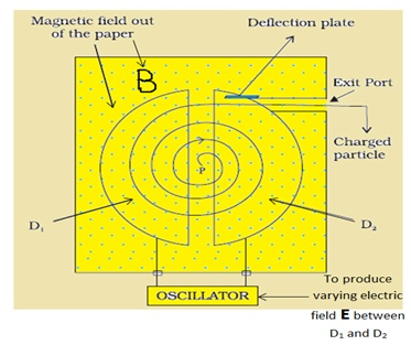
- Cyclotron is made up of 2 hollow metallic discs D1 and D2, semi-circular in shape and an oscillator.
- The discs(D) perform mainly 2 functions: a) to block(shield) electric field inside it (known as electrostatic shielding) b) act as a capacitor outside the region between the 2 discs to provide some electric field
- The oscillator’s job is to reverse the direction of electric field at the time interval of eachrevolution of charge, meaning frequency of oscillator fo should be same as the frequency of cyclotron fo.It is because when the charge moves from one D to another, the direction of electric field should always be such that the charge always accelerates(and never decelerates)
- So, each time the charge moves from one D to another D, its energy(or velocity) always increases because of acceleration due to force of electric field.And during its motion inside the Ds, its energy is fixed (since no electric field inside the Ds).
We know that for a charge moving at right angle to magnetic field, its velocity in circular path of radius r is given by: v = qBr/m
So, the kinetic energy K will be given by: K = mv2/2 = q2B2r2/(2m)
- The above equations clearly show that on increasing the velocity (or energy) of charge, the radius of circular path where charge revolves goes on increasing and finally, a highly energetic charged particle is collected through the exit port
- These highly energized particles are used in medical science for treatment, to study nuclear reactions in radioactivity, in particle accelerator and many other fields of study.
Numerical Problem:
1) The frequency of oscillator of a cyclotron is 12MHz, and the radius of Ds is 70cm. Calculate the operating magnetic field for accelerating electrons. Also find the kinetic energy of electron beam accelerated by the cyclotron.
Solution: Given, fc = 12MHz, r = 0.7m, me = 9.1×10⁻³¹kg, q = 1.6×10⁻¹⁹C
Time period of revolution inside cyclotron is given by: T = 2πme/(qB)
∴fc = qB/(2πme)
B = 2πmefc/q =2π×9.1×10-31×12×106/(1.6×10-19)
∴B = 4.28×10⁻⁴T = 4.28G (ans)
To find the kinetic energy of accelerated electron:
v = qBr/me
∴ K = mv2/2 = q2B2r2/(2me)
K = (1.6×10-19×4.28×10-4×0.70)2/(2×9.1×10-31) = 1.26×10⁻¹⁵J (ans)
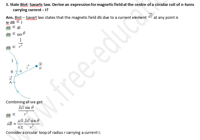
BIOT-SAVART LAW:
- We already know now that current carrying conductor generates magnetic field around themselves. Biot-Savart law just mathematically states the intensity of this magnetic field at a point.
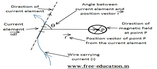
- According to the Biot-Savart law, magnetic field dBdue to current element idl, at a pointP situated at distancer from the current element idl,is:
i) directly proportional to the current element idl, ii) directly proportional to the sine of the angle (θ) between current element and r, and iii) inversely proportional to the square of the distance r between current element and the point
dB∝idl (sinθ)/r2
dB = (μo/4π)×idl×(sinθ)/r2
dB = idl × r / r3
Here proportionality constant is μo/4π = 10-7Tm/A, and μois the permeability of free space (vacuum)
COMPARISON BETWEEN BIOT-SAVART LAW AND COULOMB’S LAW:
Similarities:
- Both magnetic and electric fields at a point are inversely proportional to the square of the distance between the field source and the point in question
- Electric field due to a point charge (Coulomb’s law) is : E = (1/4πƐo) × (q/r2)
- Magnetic field due to a moving charge (Biot-Savart law) is: B = (μo/4π) × idl(sinθ)/r2

The first diagram shows the electric field (E) due to a point charge (q)
The second diagram shows the magnetic field (B) due to current carrying wire
- Both laws works on the principle of superposition (resultant field due to more than 1 sources is the vector sum of all the sources independently)
- Both magnetic and electric fields have sources that are linear in nature (both, the current element idl and the electrostatic charge q)
Differences:
- The source of electrostatic field is scalar in nature. Whereas, the source of magnetic field, which is current element (idl), is vector in nature.
- Electric field always acts along the plane containing distance (r) between point charge and the point where electric field is to be calculated. But, the magnetic field acts in the plane perpendicular to the plane of distance(r) between the current element and the concerned point.
- Magnetic field depends on the angle (θ) between the current element(idl) and line joining the point and current element. However, electric field doesn’t depend on angle(θ).
MAGNETIC FIELD DUE TO A STRAIGHT CURRENT CARRYING WIRE:
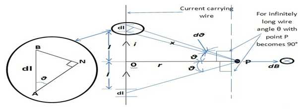
According to the Biot-Savart law, magnetic field dB at point P due to current element idl in the above diagram is given by:
∴ B = ∫(μo/4π)idlcosθ /x2 = (μo/4π)∫idlcosθ /x2……………….(i)
dB = (μo/4π)idl sin(90°-θ) /x2 = (μo/4π)idlcosθ /x2
- Considering triangle ABN:cosθ = AN/dl
AN = dl cosθ
- Considering triangle ANP: sin(dθ)˜dθ = AN/x
AN = x(dθ)
- Using the value of ANfrom the above 2 equations:
dlcosθ = xdθ……………………..(ii)
- Considering triangle AOP:cosθ = r/x
∴x = r/cosθ…………………(iii)
- Using the values of dlcosθ from eq.(ii) and x from eq.(iii) in eq.(i):
B = ∫(μo/4π)ixdθ/x2 = ∫(μo/4π)idθ/x = ∫(μo/4π)i(cosθ)dx/r
∴ B = (μo/4π)(sinθ2 + sinθ1)
- For infinitely long wire (θ1 = 90° θ2 = 90°):The above equation becomes
∴ B = μoi/(2πr)
Numerical Problem:
1) A long straight wire is carrying a current of 50A in the plane of paper in north-south direction. Find the magnitude and direction of magnetic field at a point 2.5meast of the wire.
Solution:

Given: i = 50A, r = 2.5m
The magnetic field due to long wire is given by:
B = μoi/(2πr) = 4π×10-7×50/(2π×2.5) = 4×10⁻⁶T = 0.04G (ans)
The direction will be given by cross product of current element and position vector of point from the current element (idl x r), which isgiven by Fleming’s right hand thumb rule, and it will be normal to the plane of paper coming outwards ().
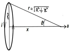
MAGNETIC FIELD ON THE AXIS OF A CIRCULAR CURRENT LOOP:
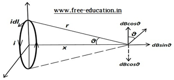
Magnetic field dB atpoint P due to current element idl, making right angle to the line joining point P and current element, will be given by Biot-Savart law as:
dB = (μo/4π)idl sin(90°)/r2 = (μo/4π)idl/r2
- As we can see in the diagram, the magnetic field dB will have 2 component, i) the vertical component dBcosθ, and ii) the horizontal component dBsinθ
- It is also evident from the diagram that the vertical component dBcosθwill be cancelled by the equal and opposite component due to current element at the opposite of the above current element (due to symmetry).
- So, the total magnetic field will only be due to the horizontal component (dBsinθ) along the positive x-axis
dBsinθ = (μo/4π)idl(sinθ)/r2
sinθ =R/r = R/√(x2 + R2)
∴dBsinθ = (μo/4π)iRdl/(x2 + R2)3/2
- So, the total magnetic field will be:
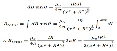
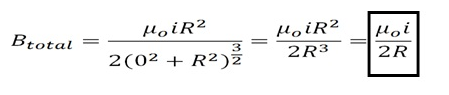
For magnetic field at the center of current loop(x = 0):
Numerical Problem: 1) A circular coil of wire has 100 turns of radius 8cm, and carrying a current of 0.4A in clockwise direction when viewed from the right side. Find the magnitude and direction of magnetic field: i) at the center of coil, and ii) at a distance of 20cm from the center of coil towards the right and normal to the coil.
Solution: Given, N = 100, r = 0.08m, i = 0.4A, x = 0.2m 0.2m
- i) Magnetic field at the center of circular coil is given by:
B = μoNi/(2r)
B = 4π×10-7×100×0.4/(2×0.08) = 3.14×10⁻⁴T = 3.14G (ans)
Direction of magnetic field will be normal to the plane of coil, and from right to leftt side of coil.
- ii) Magnetic field at an axial distance from center of coil is given by:
B = μoNiR2/(x2 + R2)(3/2)
B = 4π×10-7×100×0.4×0.0064/(0.0064 + 0.0400)(3/2) = 3.22×10⁻⁷/0.00999
∴ B = 3.22×10⁻⁵T = 0.322G (ans)
AMPERE’S CIRCUITAL LAW:
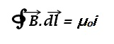
- Ampere’s circuital law states that line integral of magnetic field forming a closed loop around the current(i) carrying wire, in the plane normal to the current, is equal to the μo times the net current passing through the close loop.
Here μo = permeability of free space = 4π×10-15N/A2
- This law is based on the assumption that the closed loop consists of small elemental parts of length dl, and the total magnetic field of the closed loop will be the integral of magnetic field and the length of these elements This closed loop is called Amperian loop
- Further, this integral will be equal to the multiplication of net current passing through this closed loop and the permeability of free space(μoi)
Proof-1(Regular coil):

To prove: ∫B.dl = μoi
Starting from the left hand side, we can see in the diagram that angle between the element dl and magnetic field B is 0°
We know that magnetic field due to a long current carrying wire is:
B = μoi/(2πr)
Also, the integral of element will form the whole circle of circumference (2πr):
∫ dl = 2πr
Now putting the value of B and ∫ dl in the equation, we get:
B∫ dl = μoi/(2πr) × 2πr = μoi
∴∫B.dl = μoi
Proof-2(Irregular coil):

To prove: ∫B.dl = μoi
Starting from the left hand side:
∫B.dl1 = ∫μoi/(2πr1) × dl1
We know that: dθ1 = dl1/r1
∴∫μoi/(2πr1) × dl1 =μoi/(2π)∫dθ1 = μoi
∫B.dl = μoi
Note:
- The above two derivations proves that magnetic field at a point doesn’t depend on the shape of the Amperian loop.
- Magnetic field is same at every point in the Amperian loop (magnetic field possesses cylindrical symmetry)
- Direction of magnetic field at any point on the Amperian loop is tangential to the circle formed at that point with wire passing through the center, and the direction could be calculated by right hand thumb rule where, on holding the current carrying wire such that the extended thumb shows the direction of current in the wire, then the curling of rest of the 4 fingers represent the direction of rotation of magnetic field.
THE SOLENOID:
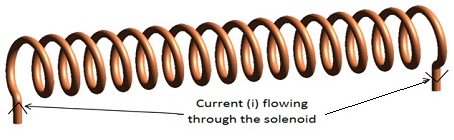
- The figure above shows a solenoid, which is actually a wire, twisted in many close circularturns, and when the length of solenoid is large compared to the radius of circular turns, then, that solenoid is known as long solenoid. We are going to discuss long solenoid in this section.
- Taking a small element dx from the solenoid of n number of turns per unit length, at a distance x from the pointP inside the solenoid where magnetic field due to current i is to be calculated
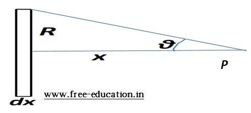
- Number of turns inside the element dx will be n×dx
- We already know that magnetic field on the axis of circular loop is given by:
dB = (μo/2) in(dx)R2/(x2 + R2)3/2
- From the above triangle, we can write:
tanθ = R/x
x = R cotθ
- On differentiating: dx = -R (cosec2θ) dθ
- Putting the value of x and dx in the equation of dB, we get:
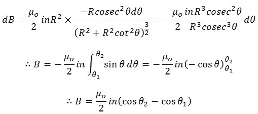
- Putting the values of θ1 = 180°, and θ2 = 0°, we get:
B = (μo/2) in(cos0° – cos180°) = (μo/2) 2in = μoni
∴ B = μoni
- For magnetic field at the end (corner) of the solenoid (θ1 = 90°, θ2 = 0°)
∴ B = μoni/2
- Note: In the above equations n = number of turns per unit length
- For any point outside the solenoid, the magnetic field is 0(for ideal solenoid)
- Solenoids are used in electromagnets, transformers etc.
THE TOROID:
- A toroid is simply a solenoid bent into a closed circular loop
- As toroid has no end points, magnetic flux leakage (loss) is minimized, and hence flux linkage is maximized as compared to a solenoid.
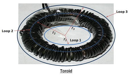
- Case-1:Magnetic field at a point in the empty space inside the toroid. We will take an Amperian loop (loop 1). By the Ampere’s circuital law:
We can see in the diagram above that current passing through the inside of the loop 1 is 0
∫B1.dl = μo×0 = 0
∴ B1 = 0
- Case-2:Magnetic field at a point inside the toroid (between the turns). We will take another Amperian loop (loop2) of radius r2. By the Ampere’s circuital law:
We can see in the diagram above that net current passing through the inside of the loop 2 is Ni, where N is the total number of turns in the toroid
B2∫dl = μo×Ni
B22πr2 = μoNi
∴ B2 = μoNi/(2πr2) = μoni
Here n = number of turns per unit length of toroid = N/(2πr2)
Note: The equation of magnetic field due to toroid is same as that of magnetic field due to solenoid.
- Case-3:Magnetic field at a point outside the toroid. We will take another Amperian loop (loop3) of radius r3. By the Ampere’s circuital law:
We can see in the diagram above that net current passing through the inside of the loop 2 is 0 (Ni current going out of the loop, and Ni current entering the loop, so net current is o)
∫B3.dl = μo×0 = 0
∴ B3 = 0
- Toroid are used in toroidal transformers, toroidal inductors etc.
Numerical Problem:
1)Using Ampere’s circuital law, derive the magnetic field inside the solenoid of length L, carrying current i and having N number of turns.
Solution:
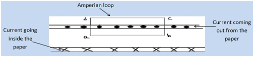
Using Ampere’s circuital law:
iL = iNl/LConsidering the Amperian loop abcd of sides l each, current passing through the loop will be:
ba∫B.dl + cb∫B.dl + dc∫B.dl +ad∫B.dl = μoNil/L
Blcos0 + Blcos90 + 0lcos180 + Blcos270 = μoNil/L
Bl = μoNil/L
∴ B = μoNi/L = μoni
2)A closely wound solenoid has length of 80cm, and radius of 0.9cm with 5 layers of windings of 400 turns each. The current flowing through the solenoid is 8A. Find the magnitude of magnetic field inside the solenoid: i) at the center, and ii) at an end of solenoid.
Solution: Given, L = 0.8m, r = 0.009, N = 5×400 = 2000, i = 8A
Number of turns per unit length (n) = 2000/0.8 = 2500/m
- i) Magnetic field at the center of solenoid is given by:
B = μoni = 4π×10-7×2500×8 = 0.0251T = 251G (ans)
- ii) Magnetic field at one end of the solenoid is given by:
B = μoni/2 = 0.0251/2 = 0.01255T = 125.5G (ans)
3) A toroid has inner radius 25cm and outer radius 26cm, with 3500 turns and 11A current flowing through it. Find the magnetic field:i) inside the core of the toroid,ii) outside the toroid and iii) in the empty space surrounded by the toroid.
Solution: Given, r1= 25cm, r2 = 26cm, N = 3500, i = 11A

R = r1 + (r2 – r1)/2 = 25 + (26-25)/2 = 25.5cm
Number of turns per unit length (n) = N /(2πR)
∴ n = 3500/(2π×0.255) = 2184.5/m
i) Magnetic field inside the core of toroid is given by:
B = μoni = 4π×10-7×2184.5×11 = 0.0302T = 302G (ans)
ii) Magnetic field outside the toroid is zero because net current through the Amperian loop(1) is zero, hence, by ampere circuital law:
B = 0 (ans)
iii) Magnetic field inside the empty space surrounded by toroid is zero because net current through the Amperian loop(3) is zero, hence, by ampere circuital law:
B = 0 (ans)
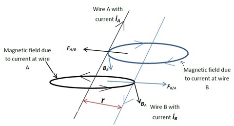
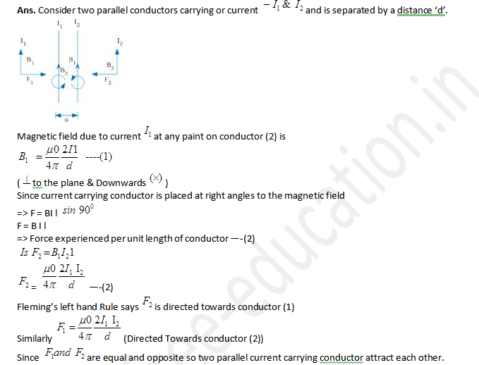
FORCE BETWEEN TWO PARALLEL CURRENT CARRYING WIRES:
Case-1: Parallel wire carrying currents in the same direction
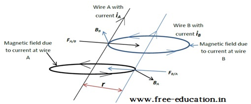
- When 2 parallel, current carrying wires are placed at some distance r from each other, they will experience a force on each other, due to magnetic field produced by each other
- Let the wires A and B, carrying current iA and iB respectively are placed r distance apart and parallel to each other
Magnetic field(BB) at any point on wire A due to current iB on wire B will be perpendicular to the plane having both wires and in the upwards direction (direction given by right hand thumb rule)
BB = μoiB/(2πr)
Force per unit length (FA/B)on wire A due to magnetic field (BB) produced by wire B will be given by:
FA/B =iABB sin90° = iABB
∴ FA/B =μoiAiB/(2πr)
The direction of FA/B will be perpendicular to wire A and towards wire B (by using Fleming’s right hand thumb rule to find cross product direction, already discussed)
Magnetic field(BA) at any point on wire B due to current iA on wire A will be perpendicular to the plane having both wires and in the downwards direction (direction given by right hand thumb rule)
BA = μoiA/(2πr)
Force per unit length (FB/A) on wire B due to magnetic field (BA) produced by wire A will be given by:
FB/A = iBBA sin90° = iBBA
∴ FA/B = μoiAiB/(2πr)
The direction of FB/A will be perpendicular to wire B and towards wire A (by using Fleming’s right hand thumb rule to find cross product direction, already discussed):
- Note: Both the forces FA/B and FB/Aare equal and towards each other, meaning the both the current carrying wires will be attracted towards each other
- In the above equation of force F, putting iA = iB = 1A,and r = 1m
F = μo×1×1/(2π×1) =μo/(2π) = 4π×10-7/(2π)
∴ F = 2×10⁻⁷N/m
- So, we can define 1Ampere current as the amount of current flowing in the 2 parallel straight wires placed 1meter apart, when the force acting on each wire per unit length is equal to the 2×10⁻⁷N/m
Case-2: Parallel wire carrying currents in the opposite direction:
- On proceeding in the similar manner as the first case, we will find that the values of forces will be the same, only their directions get reversed (refer the diagram above)
- The forces will be equal but this time away from each other, i.e., the wires will move away from each other (repel each other)
Numerical Problem:
1) Two parallel straight wires A and B, of length 10cm are carrying currents of 8A and 5A respectively in the same direction. The distance between the wires is 4cm. Find the force acting on wire A due to wire B. Will the force acting on wire B due to wire A be the same as the above answer?
Solution: Given, L = 0.1m, iA = 8A, iB = 5A, r = 0.04m
Force between two straight, parallel current carrying wires is given by:
F = μoiAiBL/(2πr) = 4π×10-7×8×5×0.1/(2π×0.04) = 2×10⁻⁵N
∴F = 2×10⁻⁵N, directed towards wire B (ans)
Yes, the force acting on wire A due to wire B will be equal to the force on wire B due to A.
TORQUE ON A CURRENT LOOP:
- We already know that a current carrying wire experiences a force when placed in external magnetic field (in direction other than the magnetic field lines). In this section we will discuss what happens when a current loop is places in the external magnetic field
- A rectangular loop of vertical dimension b and horizontal dimension a, carrying currenti, is placed in an external magnetic field B as shown below:
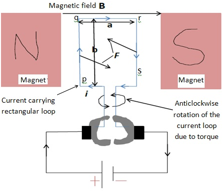
Force on a current i carrying conductor of length l making an angle θ with the external magnetic field B is given by: F = ilBsinθ
For section pq of wire, length = b, current = i, angle θ = 90°. So, force will be:
Fpq = ibB sin90° = ibB(perpendicular to the plane of paper inwards)
For section qr of wire, length = a, current = i, angle θ = 0°. So, force will be:
Fqr = ibB sin0° = 0
For section rs of wire, length = b, current = i, angle θ = 90°. So, force will be:
Frs = ibB sin90° = ibB(perpendicular to the plane of paper outwards)
For section sp of wire, length = a, current = i, angle θ = 0°. So, force will be:
Fsp = ibB sin0° = 0
Hence, the net force on the current loop pqrs will be:
Fnet = Fpq + Fqr + Frs + Fsp = ibB + 0 + (-ibB) + 0
∴Fnet = 0
- Hence, no net force acting on the rectangular loop
- But the force on pq and rs are equal and opposite and acting on 2 different points of a body so together they constitute a couple. Hence, the net torqueԏon the loop pqrs due to couple will be:
ԏ = F×a = i(ba)B = iAB = mB
Here, A = ab = area of the loop pqrs, and m = magnet moment = iA(having direction same as the area vector of the loop, i.e. perpendicular to the plane of paper outwards)

If the plane of the loop is rotated by angle θ in clockwise direction from bottom, then the area vector (or magnetic moment vector) would make an angle θ with the magnetic field lines, then the torque would be given by:
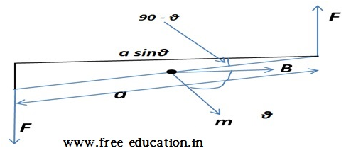
ԏ = F×asinθ = i(ba)B sinθ = iABsinθ = mBsinθ
- The above equation shows that torque depends on the angle θ between magnetic moment and magnetic field.
- Torque will be maximum when θ = 90°(magnetic moment is normal to the magnetic field)
- Torque will be minimum (ԏ = 0) when θ = 0° or 180° (magnetic moment is parallel or antiparallel to the magnetic field). In this case, the system is said to be in equilibrium.
- In the case of θ = 0°, the system will be in stable equilibrium, i.e. if the loop is given a small angular displacement, the loop will come back to the initial position and angle will be 0 again
- In the case of θ = 180°, the system is said to be in the unstable equilibrium, i.e. if the loop is given a small angular displacement, the angular displacement will increase further
Note: For N number of turns, the magnetic moment will be given by:
m = NiA
- The above equation of torque on a loop in a magnetic field is comparable to the torque on a dipole in an electric field:
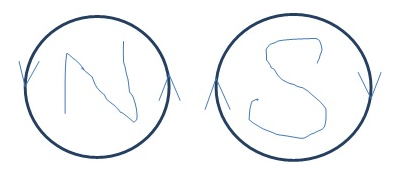
Hence, we can see that current loop behaves as a magnetic dipole with when viewed as anticlockwise current loop representing north pole, and when viewed as clockwise current loop representing south pole
Numerical Problem:
1) A square coil of side 10cm, having 20turns and carrying a current of 12A, is suspended vertically, and normal to the plane of coil makes an angle of 30° with the uniform magnetic field of 0.8T. Calculate the magnitude of torque experienced by the coil.
Will the answer change if square coil is replaced by any other coil of same area, other values being fixed?
Solution: Given, L = 0.1m, N = 20, i = 12A, θ = 30°, B = 0.8T
The torque experienced by the coil is given by:
ԏ = NiABsinθ = 20×12×(0.1×0.1)×0.8×sin30° = 0.96Nm
∴ԏ = 0.96Nm (ans)
The answer will still be the same if shape of coil is changed, because torque depends on the net area of loop (which is fixed).
CIRCULAR CURRENT LOOP AS A MAGNETIC DIPOLE:
- After the above discussion, now we know that current loop behaves as a magnetic dipole. In this topic we will discuss about the circular current loop
- Magnetic field at a distance x on the axis passing through the center of the of the circular current(i) carrying loop and normal to the plane of loop is given by:
B = μoiR2/2(x2 + R2)3/2
- If the point is very far from the current loop (x ˃˃ R), then the magnetic field will be:
B = μoiR2/(2x3)
Multiplying numerators and denominators by π:
B = μoiπR2/(2πx3)
B = μoiA/(2πx3) =μom/(2πx3)
∴ B = μo2m/(4πx3)
- Comparing the above equation to the electric field E due to electric dipole of moment p at an axial point:
E = 2p/(4πƐox3)
- We can observe that
- magnetic dipole moment m and electric dipole moment p are comparable
- permeability of free space μo and inverse of permittivity of free space 1/Ɛo are comparable
- Using the above comparison, we can also use the value of electric field E due to electric dipole of moment p at an equatorial point to evaluate the magnetic field at the equatorial point
E = p/(4πƐox3)
∴ B = μom/(4πx3)
MAGNETIC DIPOLE MOMENT OF REVOLVING ELECTRON:
- We all know that a moving charge constitutes current. Same can be said about an electron revolving around a nucleus
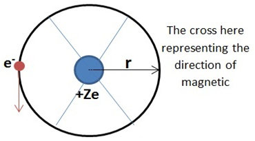
- For an electron of charge e revolving around a nucleus of charge Ze at an orbit of radius r, with velocity v magnetic moment μl is calculated by the following method:
First, we will find the current i due to electron revolution:
i = e/T
T = 2πr/v
∴i = ev/(2πr)
Now, we know that magnetic moment μl is given by:
μl = iA= iπr2
μl = ev/(2πr) × πr2 = evr/2
On multiplying and dividing by mass of electron me, we get :
μl = emevr/(2me)
Here, mevr = L (angular momentum of electron, perpendicular to the plane of paper outwards)
∴μl = -eL/(2me)
Where, minus sign signifies that angular momentum’s direction is opposite to the magnetic moment’s direction.
- Note: The above equation can be rearranged as:
μl/L = e/(2me)
- Here, the ratio μl/L is a constant (evident from left hand side of equation, which is also a constant), and this ratio is known as gyromagnetic ratio (8×10¹⁰C/kg).
MOVING COIL GALVANOMETER:
- Moving coil galvanometer is an electromagnetic device that can measure small values of current. It is also known as Weston galvanometer.
- It works on the principle that when a current loop is placed in an external magnetic field, it experiences torque, and the value of torque can be changed by changing the current in the loop
- Moving coil galvanometer consists of permanent horse-shoe magnets, coil, soft iron core, pivoted spring, non-metallic frame, scale and pointer
- We know that a current loop having N number of turns,and the cross sectional area A, carrying current i, when placed in and along the direction of external magnetic field B, experiences a torque given by:
ԏ = NiAB
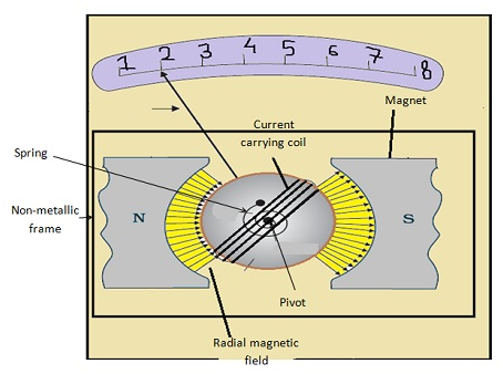
The pivoted spring of spring constant k would oppose the above torque with restoring torque C given by: C = kΦ
Here, Φ is the angular deflection of spring
- Both, the torque, and the restoring torque would be equal:
kΦ = NiAB
Φ = NiAB/k
- In the above equation, except for current, every other quantity on the right hand side is constant for a galvanometer, hence:
Φ ∝ i
- So, the angular deflection Φ produced in the pointer could be measured in terms of current in the scale calibrated on the basis of above equations.
- To use galvanometer as an ammeter (to measure higher values of current), we need to connect a shunt wire, with very small resistance(Rs), in parallel with the galvanometer (which have very low resistance of Rg
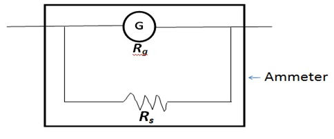
Equivalent resistance R of ammeter will be:
R = RgRs/(Rg + Rs)
Rg ˃˃ Rs
∴ R = RgRs/Rg = Rs
- So, the equivalent resistance of ammeter is very less, which is a must for sensitivity of ammeter to be higher. Also, most of the current will pass through the shunt, thus protecting the galvanometer from any damage.
- Ammeter is connected in series with the circuit where current is to be measured
- Current sensitivity(deflection per unit current) of galvanometer is given by:
Φ/i = NAB/k
- To use galvanometer as a voltmeter, we need to connect a wire, with very high resistance(Rw˃˃Rg), in series with the galvanometer to ensure that our voltmeter equivalent resistance is high and so that it will draw a very small current. Equivalent resistance will be given by:
R = Rg + Rw = Rw
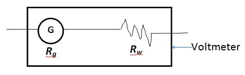
Voltmeter is connected in parallel with the circuit where voltage is to be measured
- Voltage sensitivity (deflection per unit voltage) of galvanometer is given by:
Φ/V = NAB/(kR)
Numerical Problem:
1) 2 moving coil galvanometers M1 and M2(having the same spring constants), have the following specifications: R1 = 10Ω, N1 = 30, A1 = 3.6×10⁻³m2, B1 = 0.25T
R2 = 14Ω, N2 = 42, A2 = 1.8×10⁻³m2, B2 = 0.5T
Find the ratios of current and voltage sensitivities between the 2 galvanometers.
Solution: current sensitivity is given by:
Φ/i = NAB/k
(Φ/i)1 = (30×3.6×10-3×0.25)/k
(Φ/i)2 = (42×1.8×10-3×0.5)/k
∴(Φ/i)1/(Φ/i)2 = (30×3.6×10-3×0.25)/(42×1.8×10-3×0.5) = 5/7 (ans)
Voltage sensitivity is given by:
Φ/V = NAB/(KR)
(Φ/V)1 = (30×3.6×10-3×0.25)/(k×10)
(Φ/V)2 = (42×1.8×10-3×0.5)/(k×14)
∴ (Φ/V)1/(Φ/V)2 = (30×3.6×10-3×0.25×14)/(42×1.8×10-3×0.5×10) = 1 (ans)
Chapter-4-Moving-Charge-MagnetismMoving Charge And Magnetism
Multiple Choice Questions I
4.1. Two charged particles traverse identical helical paths in an opposite sense in a uniform magnetic field

a) they have equal z-components of momenta
b) they must have equal charges
c) they necessarily represent a particle-antiparticle pair
d) the charge to mass ratio satisfy: (e/m)1 + (e/m)2 = 0
Answer:
d) the charge to mass ratio satisfy: (e/m)1 + (e/m)2 = 0
4.2. Biot-Savart law indicates that the moving electrons produce a magnetic field B such that
a) B ┴ v
b) B ‖ v
c) it obeys inverse cube law
d) it is along the line joining the electrons and point of observation
Answer:
a) B ┴ v
4.3. A current circular loop of radius R is placed in the x-y plane with centre at the origin. Half of the lop with x > 0 is now bent so that it now lies in the y-z plane.
a) the magnitude of magnetic moment now diminishes
b) the magnetic moment does not change
c) the magnitude of B at (0,0,z),z >> R increases
d) the magnitude of B at (0,0,z),z >> R is unchanged
Answer:
a) the magnitude of magnetic moment now diminishes
4.4. An electron is projected with uniform velocity along the axis of a current-carrying long solenoid. Which of the following is true?
a) the electron will be accelerated along the axis
b) the electron path will be circular about the axis
c) the electron will experience a force at 45o to the axis and hence execute a helical path
d) the electron will continue to move with uniform velocity along the axis of the solenoid
Answer:
d) the electron will continue to move with uniform velocity along the axis of the solenoid
4.5. In a cyclotron, a charged particle
a) undergoes acceleration all the time
b) speeds up between the dees because of the magnetic field
c) speeds up in a dee
d) slows down within a dee and speeds up between dees
Answer:
a) undergoes acceleration all the time
4.6. A circular current loop of magnetic moment M is in an arbitrary orientation in an external magnetic field B. The work done to rotate the loop by 30o about an axis perpendicular to its plane is
a) MB
b) √3 MB/2
c) MB/2
d) zero
Answer:
d) zero
Multiple Choice Questions II
4.7. The gyro-magnetic ratio of an electron in an H-atom, according to Bohr model is
a) independent of which orbit it is in
b) negative
c) positive
d) increases with the quantum number n
Answer:
a) independent of which orbit it is in
b) negative
4.8. Consider a wire carrying a steady current, I placed un a uniform magnetic field B perpendicular to its length. Consider the charges inside the wire. It is known that magnetic forces do not work. This implies that
a) motion of charges inside the conductor is unaffected by B since they do not absorb energy
b) some charges inside the wire move to the surface as a result of B
c) if the wire moves under the influence of B, no work is done by the force
d) if the wire moves under the influence of B, no work is done by the magnetic force on the ions, assumed fixed within the wire
Answer:
b) some charges inside the wire move to the surface as a result of B
d) if the wire moves under the influence of B, no work is done by the magnetic force on the ions, assumed fixed within the wire
4.9. Two identical current-carrying coaxial loops, carry current I in an opposite sense. A simple amperian loop passes through both of them once. Calling the loop as C,
a)
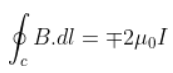
b) the value of

is independent of sense of C
c) there may be a point on C where B and dl are perpendicular
d) B vanishes everywhere on C
Answer:
b) the value of
is independent of sense of C
c) there may be a point on C where B and dl are perpendicular
4.10. A cubical region of space is filled with some uniform electric and magnetic fields. An electron enters the cube across one of its faces with velocity v and a positron enters via opposite face with velocity –v. At this instant,
a) the electric forces on both the particles cause identical acceleration
b) the magnetic forces on both the particles cause equal accelerations
c) both particles gain or lose energy at the same rate
d) the motion of the centre of mass (CM) is determined by B alone
Answer:
b) the magnetic forces on both the particles cause equal accelerations
c) both particles gain or lose energy at the same rate
d) the motion of the centre of mass (CM) is determined by B alone
4.11. A charged particle would continue to move with a constant velocity in a region wherein,
a) E = 0, B ≠ 0
b) E ≠ 0, B ≠ 0
c) E ≠ 0, B = 0
d) E = 0, B = 0
Answer:
a) E = 0, B ≠ 0
b) E ≠ 0, B ≠ 0
d) E = 0, B = 0
Very Short Answers
4.12. Verify that the cyclotron frequency ꞷ = eB/m has the correct dimensions of [T]-1.
Answer:
The path traced by the particle in a cyclotron is a circular path in which magnetic force acts as a centripetal force
mv2/R = evB
eB/m = v/R = ꞷ
B = F/ev = [MLT-2]/[AT][LT-1] = [MA-1T-2] [ꞷ] = [eB/m] = [v/R] = [T]-1
4.13. Show that a force that does no work must be a velocity dependent force.
Answer:

4.14. The magnetic force depends on v which depends on the inertial frame of reference. Does then the magnetic force differ from inertial frame to frame? Is it reasonable that the net acceleration has a different value in different frames of reference?
Answer:
The net acceleration can have a different value in different frames of reference as velocity depends on frame of reference.
4.15. Describe the motion of a charged particle in a cyclotron if the frequency of the radio frequency (rf) field were doubled.
Answer:
When the frequency of the radio frequency field was doubled, the time period of the radio frequency is halved which results in half revolution of the charges.
4.16. Two long wires carrying current I1 and I2 are arranged as shown in the figure. The one carrying I1 is along is the x-axis. The other carrying current I2 is along a line parallel to the y-axis given by x = 0 and z = d. Find the force exerted at O2 because of the wire along the x-axis.
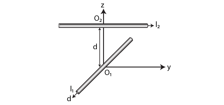
Answer:
The magnetic field B on a current-carrying conductor is given as F = I(L×B) = ILB sinθ
O2 and I1 are parallel to the y-axis and are in the direction of –Y
I2 is parallel to the y-axis and is along Y-axis therefore, the angle between I2 and B1 is zero. The magnetic force F2 is given as F2 = B1I2L1 sin 0o = 0
Therefore, the force on O2 has current I1 zero.
Short Answers
4.17. A current-carrying loop consists of 3 identical quarter circles of radius R, lying in the positive quadrants of the x-y, y-z, and z-x planes with their centres at the origin, joined together. Find the direction and magnitude of B at the origin.
Answer:
The vector sum of the magnetic field at the origin due to the quarter is given as
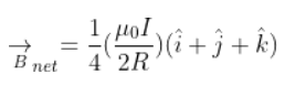
4.18. A charged particle of charge e and mass m is moving in an electric field E and magnetic field B. Construct dimensionless quantities and quantities of dimension [T]-1.
Answer:
mv2/R = evB
eB/m = v/R = ꞷ
B = F/ev = [MA-1T-2] [ꞷ] = [eB/m]=[v/R] = [T-1]
4.19. An electron enters with a velocity v = v0i into a cubical region in which there are uniform electric and magnetic fields. The orbit of the electron is found to spiral down inside the cube in the plane parallel to the x-y plane. Suggest a configuration of fields E and B that can lead to it.
Answer:
The configuration of the fields E and B are the spiral path.4.20. Do magnetic forces obey Newton’s third law. Verify for two current elements.
4.20. Do magnetic forces obey Newton’s third law. Verify for two current elements

located at the origin and
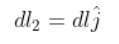
located at (0,R,0). Both carry current I.
Answer:
The magnetic forces do not obey Newton’s third law if there is no current flowing in the conductor which is placed parallel to each other.
4.21. A multirange voltmeter can be constructed by using a galvanometer circuit as shown in the figure. We want to construct a voltmeter that can measure 2V, 20V, and 200V using galvanometer of resistance 10Ω and that produces maximum deflection for a current of 1 mA. Find R1, R2, and R3 that have to be used.
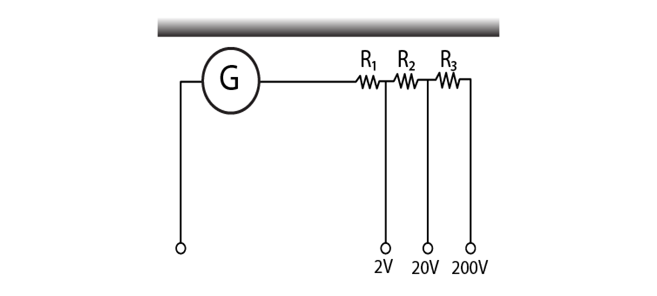
Answer:
iG(G+R1) = 2 for 2V range
iG(G+R1+R2) = 20 for 20V range
iG(G+R1+R2+R3) = 200 for 200V range
Solving the above, we get
R1 = 1990 Ω
R2 = 18kΩ
R3 = 180 kΩ
4.22. A long straight wire carrying a current of 25 A rests on a table as shown in the figure. Another wire PQ of length 1 m, mass 2.5 g carries the same current but in the opposite direction. The wire PQ is free to slide up and down. To what height will PQ rise?
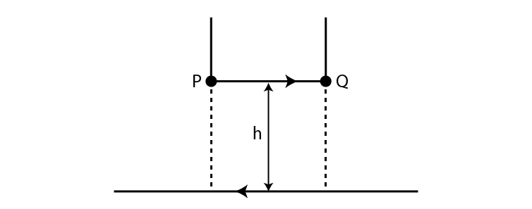
Answer:
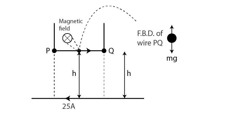
The magnetic field produced by a long straight current-carrying wire is given as
B = μ0I/2πh
Magnetic force on the small conductor is F = BIl sin θ = BIl
F = mg = μ0I2l/2πh
h = 0.51 cm
Long Answers
4.23. A 100 turn rectangular coil ABCD is hung from one arm of a balance. A mass 500 g is added to the other arm to balance the weight of the coil. A current 4.9 A passes through the coil and a constant magnetic field of 0.2 T acting inward is switched on such that only arm CD of length 1 cm lies in the field. How much additional mass ‘m’ must be added to regain the balance?
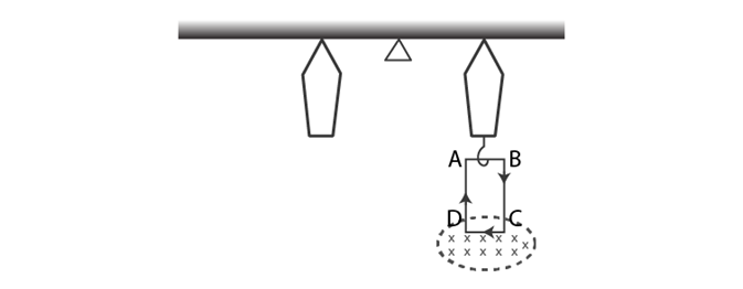
Answer:
When t = 0, the external magnetic field is off.
Mgl = Wcoil l
0.5 gl = Wcoil l
Wcoil = 0.5 9.8 N
Let m be the mass which is added to regain the balance
When the magnetic field is switched is on,
Mgl + mgl = (ILC)l
m = 1 g
4.24. A rectangular conducting loop consists of two wires on two opposite sides of length l joined together by rods of length d. The wires are each of the same material but with cross-sections differing by a factor of 2. The thicker wire has a resistance R and the rods are of low resistance, which in turn are connected to a constant voltage source Vo. The loop is placed in uniform a magnetic field B at 45oto its plane. Find τ, the torque exerted by the magnetic field on the loop about an axis through the centres of rods.
Answer:
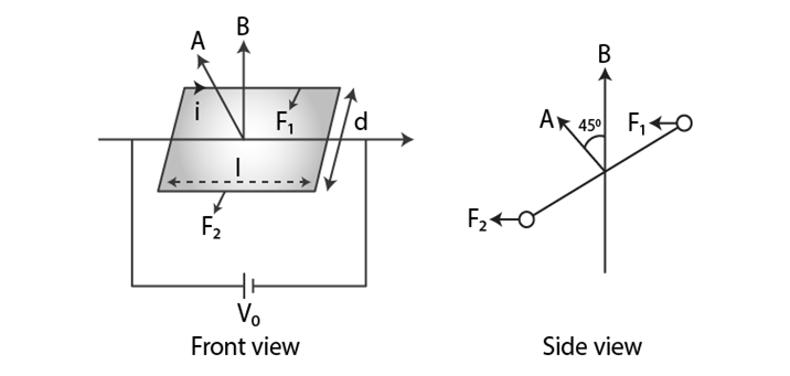
Force and torque on the first wire is given as
F1 = i1l B sin 90o = V0/2R lB
τ1= d/2√2
F1 = V0ldB/2√2 R
τ = 1/4√2 V0AB/R4.25. An electron and a positron are released from (0, 0, 0) and (0, 0, 1.5R) respectively, in a uniform magnetic field

each with an equal momentum of magnitude p = eBR. Under what conditions on the direction of momentum will the orbits be non-intersecting circles?
Answer:
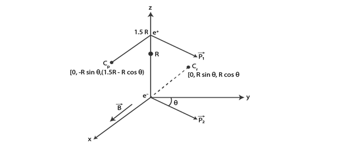
When the centres are greater than 2R, then the circular orbits of electron and positron shall not overlap.
Let d be the distance between Cp and Ce
Then d2 = 4R2 + 9/4R2 – 6R2 cosθ
As d is greater than 2R,
9/4 > 6 cos θ or cos θ < 3/8
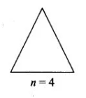
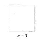
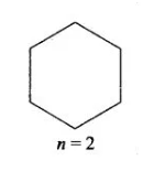
4.26. A uniform conducting wire of length 12a and resistance R is wound up as a current-carrying coil in the shape of i) an equilateral triangle of side a; ii) a square if sides a and iii) a regular hexagon of sides a. The coil is connected to a voltage source V0. Find the magnetic moment of the coils in each case.
Answer:
a) An equilateral triangle with side a
No.of loops = 4
Area of the triangle A = √3/4 a2
Magnetic moment, m = Ia2√3
b) For a square with sides a
Area, A = a2
No.of loops = 3
Magnetic moment, m = 3Ia2
c) For a regular hexagon with sides a
Area, A = 6√3/4 a2
No.of loops = 2
Magnetic moment, m = 3√3a2I
Some of the concepts that are introduced in this chapter are:
- Ampere’s circuital law
- The Solenoid and the Toroid
- Moving Coil Galvanometer
- Magnetic Force
- Magnetic Field
1 Mark Questions ( Moving Charge And Magnetism )
1. State two properties of the material of the wire used for suspension of the coil in a moving coil galvanometer?
Ans. (a) Non-Brittle conductor
(b) Restoring Torque per unit Twist should be small.
2. What will be the path of a charged particle moving along the direction of a uniform magnetic field?
Ans. The path of a charged particle will be a straight line path as no force acts on the particle.
3. Two wires of equal lengths are bent in the form of two loops. One of the loop is square shaped whereas the other loop is circular. These are suspended in a uniform magnetic field and the same current is passed through them. Which loop will experience greater torque? Give reasons?
Ans. since

Since Area of – circular loops is more Than of a square loop
Torque experienced by a circular loop is greater.
4. A cyclotron is not suitable to accelerate electron. Why?
Ans. A cyclotron is not suitable to accelerate electron because its mass is less due to which they gain speed and step out of the dee immediately.
2 Marks Questions ( Moving Charge And Magnetism )
1. A steady current flows in the network shown in the figure. What will be the magnetic field at the centre of the network?
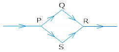
Ans. Zero, because magnetic field at the centre of the loop is just equal and opposite i.e. magnetic field due 1- PQR is equal and opposite to that of PSR.
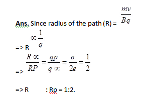
2. An – particle and a proton are moving in the plane of paper in a region where there is uniform magnetic field B directed normal to the plane of paper. If two particles have equal linear momenta, what will be the ratio of the radii of their trajectories in the field?
3. Give one difference each between diamagnetic and ferromagnetic substances. Give one example of each?
Ans. Diamagnetic substances are weakly repelled by a magnet eg. Gold.
Ferromagnetic materials are strongly attracted by a magnet eg. Iron.
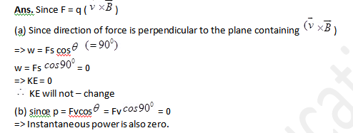
4. Write the expression for the force acting on a charged particle of charge q moving with velocity is in the presence of magnetic field B. Show that in the presence of this force.
(a) The K.E. of the particle does not change.
(b) Its instantaneous power is zero.
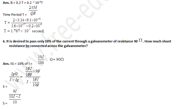
5. An electron of kinetic energy 25KeV moves perpendicular to the direction of a uniform magnetic field of 0.2 millitesla calculate the time period of rotation of the electron in the magnetic field?
3 Marks Questions ( Moving Charge And Magnetism )
1. Derive an expression for the force acting on a current carrying conductor placed in a uniform magnetic field Name the rule which gives the direction of the force. Write the condition for which this force will have (1) maximum (2) minimum value?
Ans. A conductor is placed in a uniform magnetic field which makes and angle with . Let I current flows through the conductor.

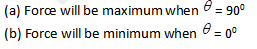


5 Marks Questions
1. (a) What is cyclotron? Explain its working principle?
(b) A cyclotron’s oscillator frequency is 10MHz what should be the operating magnetic field for accelerating protons? If radius of its dees is 20cm, what is the K.E. of the proton beam produced by the accelerator? (, ,)?
Ans. (a) It is a device used to accelerate charged particles like protons, deuterons, – particle etc.
It is based on the principle that a charged particle can be accelerated to very high energies by making it pass through a moderate electric field a number of times and applying a strong magnetic field at the same time.
(b) v = 10MHz = 10106 Hz
r = 20cm =
KE =
Since
2. (a) Draw a labelled diagram of a moving coil galvanometer. Prove that in a radial magnetic field, the deflection of the coil is directly proportional to the current flowing in the coil.
(b) A galvanometer can be converted into a voltmeter to measure upto
(i) V volt by connecting a resistance series with the coil
(ii) volt by connecting a resistance in series with coil Find R in terms of required to convert – it into a voltmeter that can read upto ‘2v’ volt.
Ans. (a) When a current I is passed through a coil two equal and opposite forces acts on the arms of a coil to form a couple which exerts a Torque on the coil.
=>
If =
is the angle made by the normal to the plane of coil with B
= NIAB —-(1)
This is called as deflecting torque
As the coil deflected the spring is twisted and a restoring torque per unit twist then the restoring torque for the deflecting & is given by
= k —-(2)
In equilibrium
Deflecting Torgue=Restoring Torgue
NIAB = K
I =
I = G where G = (galvanometer constant)
=>
Thus deflection of the coil is directly proportional to the current flowing in the coil.
(b) We know Ig =
=> Ig = —–(1)
And Ig =
Equating (1) & (2)
For conversion Ig =
=> Ig
3. Two moving coil meters, M1 and M2 have the following particulars:

(The spring constants are identical for the two meters).
Determine the ratio of (a) current sensitivity and (b) voltage sensitivity of
Ans. For moving coil meter M1:
Resistance,
Number of turns,
Area of cross-section,
Magnetic field strength,
Spring constant
For moving coil meter M2:
Resistance,
Number of turns,
Area of cross-section,
Magnetic field strength,
Spring constant,
(a) Current sensitivity of is given as:
And, current sensitivity of is given as:
Ratio
Hence, the ratio of current sensitivity of is 1.4.
(b) Voltage sensitivity for is given as:
And, voltage sensitivity for is given as:
4. In a chamber, a uniform magnetic field of 6.5 G is maintained. An electron is shot into the field with a speed of normal to the field. Explain why the path of the electron is a circle. Determine the radius of the circular orbit. (e =, me=)
Ans.Magnetic field strength, B = 6.5 G =
Speed of the electron, v =
Charge on the electron, e =
Mass of the electron,
Angle between the shot electron and magnetic field,
Magnetic force exerted on the electron in the magnetic field is given as:
F = evB
This force provides centripetal force to the moving electron. Hence, the electron starts moving in a circular path of radius r.
Hence, centripetal force exerted on the electron,
In equilibrium, the centripetal force exerted on the electron is equal to the magnetic force i.e.,
= 4.2 cm
Hence, the radius of the circular orbit of the electron is 4.2 cm.
5. In Exercise 4.11 obtain the frequency of revolution of the electron in its circular orbit. Does the answer depend on the speed of the electron? Explain.
Ans. Magnetic field strength,
Charge of the electron,
Mass of the electron,
Velocity of the electron,
Radius of the orbit, r = 4.2 cm = 0.042 m
Frequency of revolution of the electron = v
Angular frequency of the electron = = 2nv
Velocity of the electron is related to the angular frequency as:
v = r
In the circular orbit, the magnetic force on the electron is balanced by the centripetal force. Hence, we can write:
This expression for frequency is independent of the speed of the electron.
On substituting the known values in this expression, we get the frequency as:
Hence, the frequency of the electron is around 18 MHz and is independent of the speed of the electron.
6. Two concentric circular coils X and Y of radii 16 cm and 10 cm, respectively, lie in the same vertical plane containing the north to south direction. Coil X has 20 turns and carries a current of 16 A; coil Y has 25 turns and carries a current of 18 A. The sense of the current in X is anticlockwise, and clockwise in Y, for an observer looking at the coils facing west. Give the magnitude and direction of the net magnetic field due to the coils at their centre.
Ans. Radius of coil X, = 0.16 m
Radius of coil Y, = 0.1 m
Number of turns of on coil X,
Number of turns of on coil Y,
Current in coil X,
Current in coil Y,
Magnetic field due to coil X at their centre is given by the relation,
Where,
= Permeability of free space =
(towards East)
Magnetic field due to coil Y at their centre is given by the relation,
(towards East)
Hence, net magnetic field can be obtained as:
7. For a circular coil of radius R and N turns carrying current I, the magnitude of the magnetic field at a point on its axis at a distance x from its centre is given by,
(a) Show that this reduces to the familiar result for field at the centre of the coil.
(b) Consider two parallel co-axial circular coils of equal radius R, and number of turns N, carrying equal currents in the same direction, and separated by a distance R. Show that the field on the axis around the mid-point between the coils is uniform over a distance that is small as compared to R, and is given by, , approximately. [Such an arrangement to produce a nearly uniform magnetic field over a small region is known as Helmholtz coils.]
Ans. Radius of circular coil = R
Number of turns on the coil = N
Current in the coil = I
Magnetic field at a point on its axis at distance x is given by the relation,
Where,
= Permeability of free space
(a) If the magnetic field at the centre of the coil is considered, then x = 0.
This is the familiar result for magnetic field at the centre of the coil.
(b) Radii of two parallel co-axial circular coils = R
Number of turns on each coil = N
Current in both coils = I
Distance between both the coils = R
Let us consider point Q at distance d from the centre.
Then, one coil is at a distance of from point Q.
Magnetic field at point Q is given as:
Also, the other coil is at a distance of from point Q.
Magnetic field due to this coil is given as:
Total magnetic field,
For d << R, neglecting the factor , we get:
Hence, it is proved that the field on the axis around the mid-point between the coils is uniform.
8. An electron emitted by a heated cathode and accelerated through a potential difference of 2.0 kV, enters a region with uniform magnetic field of 0.15 T. Determine the trajectory of the electron if the field (a) is transverse to its initial velocity, (b) makes an angle of 30º with the initial velocity.
Ans. Magnetic field strength, B = 0.15 T
Charge on the electron,
Mass of the electron,
Potential difference, V = 2.0
Thus, kinetic energy of the electron =
……(1)
Where,
v = velocity of the electron
(a) Magnetic force on the electron provides the required centripetal force of the electron. Hence, the electron traces a circular path of radius r.
Magnetic force on the electron is given by the relation,
B ev
Centripetal force
……(2)
From equations (1) and (2), we get
= 1 mm
Hence, the electron has a circular trajectory of radius 1.0 mm normal to the magnetic field.
(b) When the field makes an angle with initial velocity, the initial velocity will be,
From equation (2), we can write the expression for new radius as:
= 0.5 mm
Hence, the electron has a helical trajectory of radius 0.5 mm along the magnetic field direction.
9. A magnetic field set up using Helmholtz coils (described in Exercise 4.16) is uniform in a small region and has a magnitude of 0.75 T. In the same region, a uniform electrostatic field is maintained in a direction normal to the common axis of the coils. A narrow beam of (single species) charged particles all accelerated through 15 kV enters this region in a direction perpendicular to both the axis of the coils and the electrostatic field. If the beam remains undeflected when the electrostatic field is, make a simple guess as to what the beam contains. Why is the answer not unique?
Ans. Magnetic field, B = 0.75 T
Accelerating voltage, V = 15
Electrostatic field, E =
Mass of the electron = m
Charge of the electron = e
Velocity of the electron = v
Kinetic energy of the electron = eV
…… (1)
Since the particle remains unelected by electric and magnetic fields, we can infer that the electric field is balancing the magnetic field.
……..(2)
Putting equation (2) in equation (1), we get
This value of specific charge e/m is equal to the value of deuteron or deuterium ions. This is not a unique answer. Other possible answers are, etc.
10. A uniform magnetic field of 1.5 T exists in a cylindrical region of radius10.0 cm, its direction parallel to the axis along east to west. A wire carrying current of 7.0 A in the north to south direction passes through this region. What is the magnitude and direction of the force on the wire if,
(a) the wire intersects the axis,
(b) the wire is turned from N-S to northeast-northwest direction,
(c) the wire in the N-S direction is lowered from the axis by a distance of 6.0 cm?
Ans.Magnetic field strength, B = 1.5 T
Radius of the cylindrical region, r = 10 cm = 0.1 m
Current in the wire passing through the cylindrical region, I = 7 A
(a) If the wire intersects the axis, then the length of the wire is the diameter of the cylindrical region.
Thus, l = 2r = 0.2 m
Angle between magnetic field and current,
Magnetic force acting on the wire is given by the relation,
F = BIl
=
= 2.1 N
Hence, a force of 2.1 N acts on the wire in a vertically downward direction.
(b) New length of the wire after turning it to the Northeast-Northwest direction can be given as:
Angle between magnetic field and current, θ = 45°
Force on the wire,
F =
= BIl
=2.1 N
Hence, a force of 2.1 N acts vertically downward on the wire. This is independent of angle because is fixed.
(c) The wire is lowered from the axis by distance, d = 6.0 cm
Suppose wire is passing perpendicularly to the axis of cylindrical magnetic field then lowering 6 cm means displacing the wire 6 cm from its initial position towards to end of cross sectional area.
= 8cm
Thus the length of wire in magnetic field will be 16 cm as AB= L =2x =16 cm
Now the force,
F = iLB as the wire will be perpendicular to the magnetic field.
The direction will be given by right hand curl rule or screw rule i.e. vertically downwards.
11. A uniform magnetic field of 3000 G is established along the positive z-direction. A rectangular loop of sides 10 cm and 5 cm carries a current of 12 A. What is the torque on the loop in the different cases shown in Fig. 4.28? What is the force on each case? Which case corresponds to stable equilibrium?
Ans.Magnetic field strength, B = 3000 G = = 0.3 T
Length of the rectangular loop, l = 10 cm
Width of the rectangular loop, b = 5 cm
Area of the loop,
= =
Current in the loop, I = 12 A
Now, taking the anti-clockwise direction of the current as positive and vise-versa:
(a) Torque,
From the given figure, it can be observed that A is normal to the y–z plane and B is directed along the z-axis.
The torque is along the negative y-direction. The force on the loop is zero because the angle between A and B is zero.
(b) This case is similar to case (a). Hence, the answer is the same as (a).
(c) Torque
From the given figure, it can be observed that A is normal to the x–z plane and B is directed along the z-axis.
The torque is along the negative x direction and the force is zero.
(d) Magnitude of torque is given as:
Torque is at an angle of with positive x direction. The force is zero.
(e) Torque
= 0
Hence, the torque is zero. The force is also zero.
(f) Torque
= 0
Hence, the torque is zero. The force is also zero.
In case (e), the direction of and is the same and the angle between them is zero. If displaced, they come back to an equilibrium. Hence, its equilibrium is stable.
Whereas, in case (f), the direction of and is opposite. The angle between them is 180°. If disturbed, it does not come back to its original position. Hence, its equilibrium is unstable.
12. A solenoid 60 cm long and of radius 4.0 cm has 3 layers of windings of 300 turns each. A 2.0 cm long wire of mass 2.5 g lies inside the solenoid (near its centre) normal to its axis; both the wire and the axis of the solenoid are in the horizontal plane. The wire is connected through two leads parallel to the axis of the solenoid to an external battery which supplies a current of 6.0 A in the wire. What value of current (with appropriate sense of circulation) in the windings of the solenoid can support the weight of the wire?
Ans.Length of the solenoid, L = 60 cm = 0.6 m
Radius of the solenoid, r = 4.0 cm = 0.04 m
It is given that there are 3 layers of windings of 300 turns each.
Total number of turns, = 900
Length of the wire, l = 2 cm = 0.02 m
Mass of the wire, m = 2.5 g =
Current flowing through the wire, i = 6 A
Acceleration due to gravity,
Magnetic field produced inside the solenoid,
Where,
= Permeability of free space =
I = Current flowing through the windings of the solenoid
Magnetic force is given by the relation, F = Bil
Also, the force on the wire is equal to the weight of the wire.
Hence, the current flowing through the solenoid is 108 A.
For Complete Notes & Important Question Check out pdf notes (click here for download)
Download Class 12 Physics Notes & Important Questions Chapter wise (Click Here)
Mohd. Sharif Qualification: B.Tech (Mechanical Engineering) [Founder of Wisdom Academy] [Aim Foundation & Free-Education.In] [Engineer By Profession | Teacher By Choice] [Blogger, YouTube Creator]