
www.free-education.in is a platform where you can get pdf notes from 6th to 12th class notes, General Knowledge post, Engineering post, Career Guidelines , English Speaking Trick , How to crack interview and lots more. ( Alternating Current )
Class 12th Physics Chapter 7 Alternating Current Notes
Introduction
- In this chapter we will study about the alternating current and their applications in our day-to-day life.
- Some of the applications of Alternating currents which can be seen in our day to day life are :- Radio, refrigerators, television, transformers, power transmission stations (which supply power in our houses), in cars etc.
- We will also try to understand the implementation of AC in all the electronic appliances which we use.

In Radio, Tuner circuit plays very important role. The tuner circuit uses LC circuit, which is same as AC circuit
In TV sets, small transisitors are used to regulate the voltage, so that TV is not harmed during voltage fluctuations
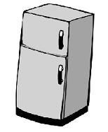
Refrigerator has inbuilt stabalizer to regulate the voltage

Most Appliances in our house use AC power supply

Voltage transmission over long distance is very important application of AC, this can’t be done with DC

Accelerators are used in the cars to charge the battery. Accelerators are application of AC
Alternating Current
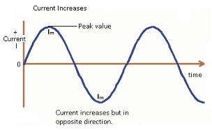
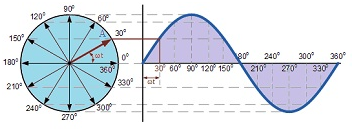
- Alternating current is defined as the current that varies like a sine function with time.
- The value of current will oscillate between a maximum value and a minimum value.
- In case of AC the current is changing its magnitude at every instant of time.
- The direction of current will be clockwise and anticlockwise and it will keep on repeating.
- Frequency of the alternating current is defined as how fast the electrons are changing their directions. For example: If frequency is 20Hz this means electrons are moving back and forth 20 times in a second.
- DC voltage gives rise to DC current similarly AC voltage give rise to AC current.
- Alternating current is expressed as: – I = Im sinωt
- Where Im = maximum or peak value of the AC .
- Alternating voltage is expressed as: – V = Vm sinωt
- Where Vm = peak value of the voltage.
Causes of alternating current
- When a rotating magnet is considered instead of steady magnetic field then both the poles of the magnet will keep on changing as a result the direction of electrons also gets reversed.
This results oscillation of electrons which give rise to current and this current is known as alternating current.

Comparison between AC and DC
| Direct Current | Alternating Current |
| Electron flow in one direction. | Electron flows in both directions. |
| Magnitude remains constant. | Magnitude varies with time. |
| Can be stored in batteries. | 3.Cannot be stored. |
| E.g. batteries | 4.AC generators & mains |
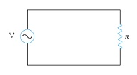
Resistive AC Circuit
- In resistive AC circuit there will be only resistors and no other circuit elements will be present.
- Consider the circuit as shown in the (fig) below .
- Input AC voltage V = Vm sinωt (equation(1))
- Where Vm = peak value of voltage. It is also known as voltage amplitude.
- Let the EMF of the voltage source = V, then by applying Kirchhoff’s loop law to the circuit, total EMF of the circuit will be V = IR
- Where I = current flowing through the circuit.
- Using equation(1), Vm sinωt = IR
- => I = (Vm/R) sinωt equation(2)
- This is the amount of current which flows through the circuit. By substituting Im = (Vm/R) in equation(2)
- Therefore I = Im sinωt
- Where Im = current amplitude or peak value of current.
Conclusion:-
If alternating voltage is applied to a circuit which has only a resistor then the current flowing through the circuit will also be alternating current.
This means the current flowing through a circuit is also a sinusoidal function.
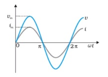
Graphical representation of voltage & current
- From the graph it is clear that although both voltage and current are sinusoidal function but the peak value of current is less than the peak value of voltage. As Im = (Vm/R) => Im < Vm.
- Voltage and current are in phase with each other which means both of them reach their maximum value, then 0 and their minimum value at the same time.
- Average current over a complete cycle is zero.
- Average voltage over a complete cycle is zero.
- V = Vm sinωt
- Where V = instantaneous value of voltage at time t.
- I = Im sinωt
- Where I = instantaneous value of current at any time t.
The given graph is showing that in a pure resistor, the voltage and current are in phase. The minima, zero and maxima occur at the same respective times.
Power associated with resistor
- The average power over one complete cycle is not equal to 0, the power dissipation is in the form of heat.
- By using Joule heating which is given as i2R ; this shows Joule heating depends on i2 and i2 is always positive.
- This shows there will be average power consumed by the pure resistive circuits.
Derivation
- Using the instantaneous values of voltage and current :-
- V = Vm sinωt ,I = Im sinωt
- Instantaneous power p = VI
- Then p = Vm sinωt Im sinωt
- p = Vm Im sin2ωt equation(1)
- Average power P = (1/T) 0T∫pdt
- where T = time period
- =(1/T) 0T∫ Vm Im sin2ωtdt using equation(1)
- =( Vm Im/T) 0T∫ (1-cos2ωt)/(2)dt using (1-cos2θ = 2sin2 θ)
- P = ( Vm Im/2T) 0T∫(1-cos2ωt) dt
- =( Vm Im/2T) [t – (sin2 ωt/2ω)]0T
- After simplifying , we will get,
- P = ( Vm Im/2)
- Or P =(1/2) Im2 R equation(2)
- The above expression shows the pure power consumed in one complete cycle in a pure resistive circuit.
- In order to represent expression of power in AC same as in DC, a new term was introduced which is known as root mean square current.
- Root mean square current (rms) is one of the ways to calculate the average value of alternating current.
- In order to make the expression of power in AC consistent with the expression of power in DC the peak value of current was replaced by the RMS value.
- Therefore equation (2) can be written as: – P= I2rmsR.
Problem:- A light bulb is rated at 100W for a 220 V supply. Find (a) the resistance of the bulb; (b) the peak voltage of the source; and (c) the rms current through the bulb.
Answer:-
We are given P = 100 W and V = 220 V. The resistance of the bulb is
R=(V)2/(P)
=(220 )2/(100W) =484
(b) The peak voltage of the source is
vm = √2V = 311V
(c) Since, P = I V
I = (P/V) = (100W)/(220V)
=0.450A
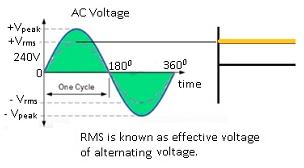
RMS voltage
- RMS means Root Mean Squared voltage. This means taking the root of the mean of the square of the instantaneous voltage.
- RMS voltage is also known as Effective voltage which is defined as the overall effective value of the alternating current or alternating voltage.
- Square root of the mean of the squared function of instantaneous values.
- For example V12, V22, V32, V42 are the instantaneous values of voltages.
- Therefore Vrms = √( V12+ V22 + V32 + V42 )/4
- It supplies the same power to the load as an equivalent DC circuit. P = Irms2R.
- This means the power which is supplied to the load will be equivalent to the DC circuit.
Graphically:-
- The RMS value of an alternating voltage will correspond to the same amount of power consumption in case of DC voltage.
- Therefore RMS is known as effective value of the alternating voltage. This shows DC voltage and RMS voltage will supply the same power in both the cases.
This RMS value will correspond to the same amount of power consumption that will be same in case of DC
Problem:–
(a) The peak voltage of an AC supply is 300 V. What is the rms voltage?
(b) The rms value of current in an AC circuit is 10 A. What is the peak current?
Answer :-
(a) Peak voltage of the ac supply, Vo = 300 V
rms voltage is given as:
V = (Vo/√2)
= (300 /√2)
= 212.1 V
(b) The rms value of current is given as:
I = 10 A
Now, peak current is given as:
Io = √2I = √2 × 10 = 14.1 A
Determining RMS voltages Vrms
Case 1:- Instantaneous discrete values:- Values are each distinguishable from the other.
- Consider the discrete values of voltages at each specific instant of time t as V1,V2,V3,–,Vn.
- Therefore Vrms = √( (V12 + V22 + V32 + V42 +…+ Vn2)/n)
Case2:- Instantaneous continuous values :- Each instant of time is not distinguishable from other instant of time.
- V = Vm sinωt this means voltage is changing at every moment. Voltage value is like a sine function.
- Vrms=√ ( (1/T) 0T∫ (V2dt))
- = √(1/T) 0T∫ Vm2 sin2ωt dt
- After simplifying the above equation:-
- Vrms = (Vm/√2)
RMS Current
- RMS current is same as Root Mean Squared current. It is the effective current.
- Square root of the mean of the squared function of instantaneous values.
- For example I12, I22, I32,…., In2 are the instantaneous values of currents.
- Irms = √(=√( I12+I22+ I32+I…. + In2)/n (For discrete values of current)
- It supplies the same power to the load as an equivalent DC circuit.
- In case of continuous values :- I = Im sinωt .
- Therefore Irms= (Im/√2) .
Overview of Irms, Iavg, Iinst
Instantaneous value of current :-
- I = Im sinωt. As (ωt) keeps changing therefore the value of I keeps on changing.
- At every instant the value of current is changing.
- Im = maximum or peak value that current can take.
RMS value :-
- Irms = (Im/ √2) .
- The RMS value is the effective value of alternating current .
Average value of current:-
- Iavg means the average value of current over one complete cycle.
- Iavg = 0.
- => Iavg = (1/T) 0T ∫ I dt
- = (1/T) 0T ∫ Im sinωt dt (Using I = Im sinωt)
- => (Im/T) [-cosωt + cos0]
After Simplifying,
- (Im/T) [-1+1]
- => Iavg = 0.
Note:- Value of alternating current keeps on changing.
Problem:-
A 100 Ω resistor is connected to a 220 V, 50 Hz ac supply.
(a) What is the rms value of current in the circuit?
(b) What is the net power consumed over a full cycle?
Answer:-
Resistance of the resistor, R = 100 Ω
Supply voltage, V = 220 V
Frequency, ν = 50 Hz
(a) The rms value of current in the circuit is given as
I=(V/R)
= (220)/(100)
= 2.20 A
(b) The net power consumed over a full cycle is given as:
P = VI = 220 × 2.2 = 484 W
Phasor diagrams
- Phasor diagrams are the representations of voltage-current relationship in AC circuits.
- A phasor is a vector capable of rotating about the origin with (angular velocity) ‘ω’.
- The vertical component of phasor will represent the sinusoidally varying quantity.
- Considering V = Vm sinωt then the vertical component represents the instantaneous value of voltage.
- The magnitude(length of the vector) of the phasor is the peak value at that instant of time.
Advantages of phasor diagram:-
It is not possible to represent the complicated relationship between the voltage and currents with the help of graphs . In that case phasor diagrams are used.
Current – Voltage representation for Resistor circuits
Inductive AC Circuit
In Inductive AC circuit only circuit element which is present is inductor.
AC voltage supplied to a inductor:-
- The source of voltage is alternating as is represented as V = Vm sinωt.
- In the circuit there is source voltage(V) and an inductor with inductance = L.
- In this circuit there are no resistors. There is one source EMF i.e. is the source voltage and another emf is self-induced.
- As current is changing therefore the magnetic flux associated with the current also changes.
- According to Faraday’s Lenz’s law whenever there is change in the flux a current is induced or an EMF is induced in the inductor.
- As a result there will be self-induced EMF in the inductor which will oppose the change which is causing it.
- Therefore V + e = 0.
- Where V = source voltage and e = self- induced emf in the inductor L.
- => V – L(dI/dt) = 0 . Using e = -L (dI/dt)
- => Vm sinωt – L(dI/dt) = 0.
- =>dI = (Vm sinωt dt /L)
- Integrating both sides , therefore 0I∫dI = ∫ (Vm sinωt dt /L)
- After simplifying, I = (Vm/L) [ -cosωt/ω] + constant
- I = – (Vm/ ω L) cosωt + 0
- (constant = 0 because as source voltage oscillate symmetrically about 0, therefore current should also oscillate about 0.)
- I = – Im cosωt
- where Im = (Vm/ ω L)
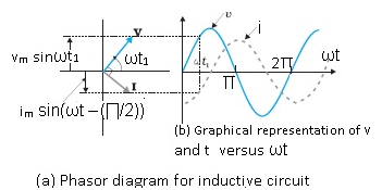
- I = Im sin(ωt –(∏/2)) . This is the current which will flow through the circuit.
Conclusion:–
The current and voltage are not in phase with each other. They are out of phase by (∏/2).
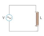
(Circuit diagram containing a voltage source and an inductor).
Inductive Reactance
- Current amplitude Im = (Vm / ω L) .
- In an inductance circuit (ω L) acts as resistance, when compared with I = (V/R). Therefore the resistance of inductive circuit is known as inductive reactance.
- Inductive reactance is the resistance associated with a pure inductive AC circuit.
- It is denoted by XL.
- S.I. unit: ohm(Ω).
- It limits the current flowing through an inductive circuit.
- XL = ω L . => XL ∝ ω and XL ∝ L.
Problem:- A 44 mH inductor is connected to 220 V, 50 Hz ac supply. Determine the RMS value of the current in the circuit.
Answer:-
Inductance of inductor, L = 44 mH = 44 × 10−3 H
Supply voltage, V = 220 V
Frequency, ν = 50 Hz
Angular frequency, ω = 2πν
Inductive reactance, XL = ω L = 2πν L = (2π × 50 × 44 × 10−3) Ω
RMS value of current is given as:
I = (V/XL)
= (220)/(2π × 50 × 44 × 10−3) = 15.92 A
Hence, the rms value of current in the circuit is 15.92 A.
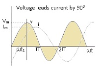
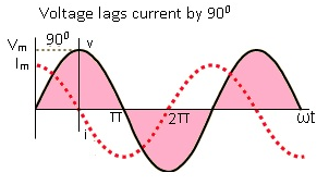
Graphical representation of Voltage & Current
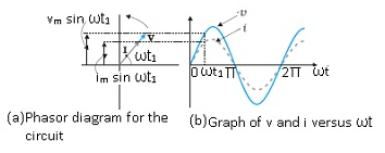
- Voltage and current are represented as:- V = Vm sinωt and I = Im sin(ωt –(∏/2)) respectively. Voltage and current are out of phase by (∏/2).
- Current lags voltage by (∏/2).Current will reach its maximum value after(∏/2).
- Average current over a complete cycle is 0.
- Average voltage over a complete cycle is 0.
Power associated with Inductor
- Voltage and current associated with the inductor V = Vm sinωt is I = Im sin(ωt –(∏/2)) respectively.
- Instantaneous power p = VI = Vm Im sinωt sin(ωt –(∏/2))
- = – Vm Im sinωt cos ωt ( using formula (sin(A –(∏/2)) = – cosA))
- After simplifying we get,
- p = – ((Vm Im sin2ωt)/(2))
- Average Power PL = (1/T) 0T∫ p dt
- =(-1/T) 0T∫ (Vm Im/2) sin2 ωt dt
- = – ( Vm Im/2T) 0T∫ sin2 ωt dt
- After simplifying we will get ,
- PL = 0.
- Therefore average power supplied to an inductor over one complete cycle is 0.
Problem:- A pure inductor of 25.0 mH is connected to a source of 220 V. Find the inductive reactance and rms current in the circuit if the frequency of the source is 50 Hz.
Answer:-
The inductive reactance,
XL = 2πν L = (2×3.14x50x25x10-3) W
= 7.85Ω
The rms current in the circuit is:- I =(V/XL) =(220V)/(7.85Ω) =28A
Problem:-A coil of inductance 0.50 H and resistance 100 Ω is connected to a 240 V,
50 Hz ac supply. (a) What is the maximum current in the coil? (b) What is the time lag between the voltage maximum and the current maximum?
Answer:-
Inductance of the inductor, L = 0.50 H
Resistance of the resistor, R = 100 Ω
Potential of the supply voltage, V = 240 V
Frequency of the supply, ν = 50 Hz
(a) Peak voltage is given as: V0=√2V
=√2 x 240 =339.41V
Angular frequency of the supply, ω = 2 πν
= 2π × 50 = 100 π rad/s
Maximum current in the circuit is given as:
I0= (V0)/( √(R)2 + ω2L2)
=(339.41)/((100)2+(100π)2+(0.50)2) = 1.82A
(b) Equation for voltage is given as:
V = V0 cos ωt
Equation for current is given as:
I = I0 cos (ωt − Φ)
Where,
Φ = Phase difference between voltage and current At time, t = 0.
V = V0(voltage is maximum)
For ωt − Φ = 0 i.e., at time ,
I = I0 (current is maximum)
Hence, the time lag between maximum voltage and maximum current is .( Φ/ω)
Now, phase angle Φ is given by the relation,
tan Φ = (ωL)/(R)
= (2 π x 50x 0.5)/(100)
=1.57
Φ = 57.50 = (57.5 π)/(180)rad
ωt = (57.5 π)/(180)
t =(57.5)/(180 x 2 π x 50)
=3.19×10⁻³ s
=3.2ms
Hence, the time lag between maximum voltage and maximum current is 3.2 ms.
Problem:- Obtain the answers (a) to (b) in previous problem if the circuit is connected to a high frequency supply (240 V, 10 kHz). Hence, explain the statement that at very high frequency, an inductor in a circuit nearly amounts to an open circuit. How does an inductor behave in a dc circuit after the steady state?
Answer:-
Inductance of the inductor, L = 0.5 Hz
Resistance of the resistor, R = 100 Ω
Potential of the supply voltages, V = 240 V
Frequency of the supply, ν = 10 kHz = 104Hz
Angular frequency, ω = 2πν= 2π × 104rad/s
- Peak voltage, V0=√2V = 240√2 V
Maximum current , I0= (V0)/( √(R)2 + ω2L2)
=(240√2) / ((100)2 + (2 π x 104)2 x(0.50)2)
=1.1 x 10⁻² A
(b) For phase difference Φ, we have the relation:
tan Φ = (ωL)/(R)
= (2 π x 104 x 0.5)/(100) =100 π
Φ =89.820 = (89.82 π)/(180) rad
ω t = (89.82 π)/(180)
t= (89.82 π)/(180×2 πx104)
=25 μ s
It can be observed that I0 is very small in this case. Hence, at high
frequencies, the inductor amounts to an open circuit.
In a dc circuit, after a steady state is achieved, ω = 0. Hence, inductor L behaves like a pure conducting object.
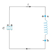
(Magnetisation and demagnetisation of a magnet)
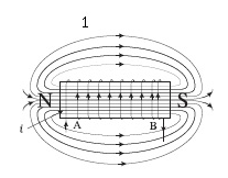
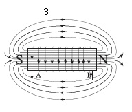
- Current i through the coil entering at point A increase from zero to a maximum value. Flux lines are set up i.e., the core gets magnetised. With the polarity shown voltage and current are both positive. So their product p is positive.
ENERGY IS ABSORBED FROM THE SOURCE.
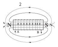
Current in the coil is still positive but is decreasing. The core gets demagnetised and the net flux becomes zero at the end of a half cycle. The voltage v is negative (since di/dt is negative). The product of voltage and current is negative, and ENERGY IS BEING RETURNED TO SOURCE.

(One complete cycle of voltage/current . It is clear that the current lags the voltage.)
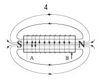
Current i becomes negative i.e., it enters at B and comes out of A. Since the direction of current has changed, the polarity of the magnet changes. The current and voltage are both negative. So their product p is positive. ENERGY IS ABSORBED.
- Current i decreases and reaches its zero value at 4 when core is demagnetised and flux is zero. The voltage is positive but the current is negative. The power is, therefore, negative. ENERGY ABSORBED DURING THE ¼ CYCLE 2-3 IS RETURNED TO THE SOURCE.
Capacitive AC Circuit
Capacitive AC circuit has an AC voltage and only circuit element present is capacitor.
AC voltage applied to a Capacitor:-
- In this circuit an alternating voltage is applied to a
- The source voltage or applied voltage V = Vm sinωt .
- In this circuit the capacitor will continuously get charged and discharged in each half
- Therefore the applied voltage V = voltage across the plates of the capacitor.
- => V = (q/C)
- Where q = charge on the capacitor.
- => Vm sinωt = (q/C)
- By differentiating the above equation,
- => C Vm d(sinωt)/dt = dq/dt
- => I = C Vm ω cosωt
- In terms of sine function :- I = C Vm ω sin(ωt + (∏/2)) (equation(1))
- Putting C Vm ω = Im = current amplitude in equation(1),
- I = Im sin(ωt + ∏/2). This is the expression for current through capacitive circuit.
Capacitive Reactance:-
- Current amplitude Im = C Vm ω
- => Vm = (1/ ω C) Im (equation(a)) ,comparing equation(a) with V = IR , the term (1/ ω C) acts as a resistance in case of capacitive circuit.
- (1 / ω C) is known as capacitive reactance. Capacitive reactance is the resistance associated with a pure Capacitive AC circuit.
- It is denoted by Xc.
- SI unit is ohm(Ω).
- Therefore Xc = (1/ ω C).
- => Xc ∝ (1/ ω) and Xc ∝ (1/C).
Graphical representation of Voltage and Current
- Voltage and current are out of phase by (∏/2). The current is ahead of voltage by (∏/2).
- Average current over a complete cycle is zero.
- Average voltage over a complete cycle is zero.
Power associated with Capacitor
- Voltage and current associated with the capacitor are given as V = Vm sinωt and I = Im sin(ωt +(∏/2)) respectively .
- Instantaneous power p = VI = Vm Im sinωt sin(ωt +(∏/2))
- Average Power PC = (1/T) 0T∫ p dt
- = (1/T) 0T∫ Vm Im sinωt sin (ωt +(∏/2)) dt
- After simplifying the above expression:-
- PC = 0. This implies the average power supplied to a capacitor over one complete cycle is zero.
Phasor diagram and Graphical representation
Problem:- A 100 μF capacitor in series with a 40 Ω resistance is connected to a 110 V,60 Hz supply. (a) What is the maximum current in the circuit? (b) What is the time lag between the current maximum and the voltage maximum?
Answer:-
Capacitance of the capacitor, C = 100 μF = 100 × 10−6F
Resistance of the resistor, R = 40 Ω
Supply voltage, V = 110 V
(a) Frequency of oscillations, ν= 60 Hz
Angular frequency ω = 2πν= 2π x 60 rad/s,
For a RC circuit, we have the relation for impedance as:
Z = √(R2 +1/(ω2C2))
Peak voltage, V0 = V√2 = 110√2
Maximum current is given as:
I0= (V0/Z)
= V0/(√(R2 +1/(ω2C2))
=(110√2)/( √ (40)2 + (1/(120 π)2 x (10-4)2)
=(110√2)/( √(1600 +(10)8/(120 π)2)
=3.24A
(b) In a capacitor circuit, the voltage lags behind the current by a phase angle of Φ. This angle is given by the relation:
tan Φ = (1/ωC)/(R) = (1/ ωCR)
=(1)/( 120 π x 10-4 x 40) = 0.6635
Φ = tan-1 (0.6635) = 33.560
=(33.560)/(180) rad
Therefore Time lag = (Φ/ω)
=(33.56 π)/(180 x 120 π)
=1.55 x 10⁻³ s
=1.55ms
Hence, the time lag between maximum current and maximum voltage is 1.55 ms.
Problem:- A 60 μF capacitor is connected to a 110 V, 60 Hz ac supply. Determine the RMS value of the current in the circuit.
Answer:-
Capacitance of capacitor, C = 60 μF = 60 × 10−6 F
Supply voltage, V = 110 V
Frequency, ν = 60 Hz
Angular frequency, ω = 2πν
Capacitive reactance, XC = (1/ωC) = 1/(2πνC)
=1/(2π × 60 × 60 × 10−6) Ω
RMS value of current is given as:
I =(V)/(XC)
= (220) /(2π × 60 × 60 × 10−6) = 2.49 A
Hence, the rms value of current is 2.49 A.
Problem:- A 15.0 μF capacitor is connected to a 220 V, 50 Hz source. Find the capacitive reactance and the current (RMS and peak) in the circuit. If the frequency is doubled, what happens to the capacitive reactance and the current?
Answer:–
The capacitive reactance is
XC = (1/ 2πνC )
=(1/2π (50Hz)(15.0×10⁻⁶F) )
=212 Ω
The RMS current is
I =(V/XC)
=(220V)/(212 Ω)
The peak current is
Im = √2 I = (1.41)(1.04A) = 1.47 A.
This current oscillates between +1.47A and –1.47 A, and is ahead of the voltage by π/2.
If the frequency is doubled, the capacitive reactance is halved and consequently, the current is doubled.
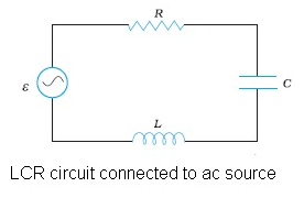
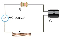
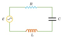
Series LCR circuit
- LCR circuit consists of inductor having inductance = L, a capacitor having capacitance = C and a resistor having resistance = R.
- As resistor, capacitor and inductor all are connected in series therefore same amount of current will flow through each of them.
- Considering source voltage V = Vm sinωt
- Applying Kirchhoff’s loop rule to this circuit :-
- Net EMF = V (source voltage) + e (self-induced emf) = IR (voltage drop across the resistor) + (q/C) ( voltage drop across the capacitor).
- => Vm sinωt – L (dI/dt) = IR +(q/C)
- => Vm sinωt = IR +(q/C) + L (dI/dt)
- By putting I = (dI/dt) :- Vm sinωt = R (dq/dt) + (q/C) + L(d2q/dt2)
- By rearranging , L(d2q/dt2) + R (dq/dt) + (q/C) = Vm sinωt (equation(1))
Impedance in a LCR circuit
- Resistance associated with the series LCR circuit is known as impedance.
- Impedance is the net resistance offered by the LCR circuit i.e. it includes the resistance offered by the resistor, inductor and the capacitor.
- It is denoted by Z.
- SI unit is ohm(Ω).
- The value of Z is given as :- Z = √(R2 + (XC – XL)2)
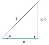
Impedance diagram:-
- It is a right angle triangle whose hypotenuse is represented by Z, base is R and the height or perpendicular is (XC – XL)2 .
- Φ = phase angle between V(source voltage) and I(current flowing through the circuit).
- I parallel to VR. Therefore Φ = angle between the V and VR.
- Z = √(R2 + (XC – XL)2) and tan Φ = (XC – XL)/(R)
Case1:– XC > XL
- (XC – XL) will be positive. Therefore Φ = (+ive).
- Circuit will be a capacitive circuit because XC is more.
- Current(I) will lead the voltage(V) .
Case 2:- XL > Xc
- (XC – XL) will be negative. Therefore Φ =(-ive).
- Circuit will be an inductive circuit because XL is more.
- Voltage(V) will lead the current(I).
AC voltage applied to a Series LCR circuit
- In order to solve the given equation L(d2q/dt2) + R (dq/dt) + (q/C) = Vm sinωt (equation(1)), we have to assume a solution for this:- q = qm sin (ωt + q )
- By Differentiating, (dq/dt) = qm ω cos(ωt + q) , and
- (d2q/dt2) = – qm ω2 sin(ωt + q) ;
- Substituting above values in (equation(1)) and simplifying we get,
- => qm ω [R cos (ωt + q) + (XC – XL) sin(ωt + q)] = Vm sinωt
- Divide and multiply by Z throughout the equation:-
- Where Z = Impedance
- => (qm ω Z) = [(R/Z) cos (ωt + q) + (1/Z)( XC – XL) sin (ωt + q) ] = Vm sinωt
- Therefore expression becomes,(using (R/Z) = cos f and (XC – XL)/(Z) = sin f)
- (qm ω Z) [cos f cos (ωt + q) + sin f sin (ωt + q)] = Vm sinωt
- (qm ω Z) [cos ( – f + ωt + q) = Vm sinωt
- Therefore, Vm = Z Im (replacing (qm ω) = Im) ,
- After calculating and simplifying, we get
- I = Im sin(ωt + f) . This is the expression for current in series LCR circuit.
Points to be noted:-
- Voltage and current are in/out of phase depends on f.
- Current Amplitude is given by: Im = qm ω.
- This is because V = Vm sinωt and current I = Im sin(ωt + f).
- If f =0 then voltage and current are in phase with each other.
- If f = (∏/2) then voltage and current are out of phase with each other.
- Equation for series LCR circuit resembles that of a forced, damped oscillator.
Phasor diagram for Series LCR circuit
- Resistor, inductor and capacitor all are in series.
- Source voltage V = Vm sinωt and current I = Im sin (ωt + f).
- VL = voltage across inductor, VC =voltage across capacitor, VR = voltage across resistor and V = source voltage.
- Peak values: – VL = Im XL , VC = ImXC , VR = ImR and V =Vm .
- Resistor VR and I are in phase .Inductor I lag behind the VL.
- In Capacitor VC lag behind the IL.
- From the phasor diagram we can see that the VL and VC are exactly in opposite direction with each other and are in same line.
- The length of the phasors represents the peak values (Im XL, ImXC and ImR) .
- From the circuit , VR + VC + VL = V.
- Refer figure(2) from the phasors a right triangle is obtained whose hypotenuse =V .
- Using Pythagoras theorem, V2R + (VC – VL)2 = V2m
- V2m = (ImR)2 + [ImXC – Im XL]2
- = I2mR2 + I2m(XC – XL)2
- V2m = I2m [R2 + (XC – XL)2]
- Vm = Im √( R2 + (XC – XL)2)
- Comparing the above equation with V=IR , then R = √( R2 + (XC – XL)2).
- Therefore Z = √( R2 + (XC – XL)2)
(a) Relation between the phasors VL, VR, VC, and I,
(b) Relation between the phasors VL, VR, and (VL + VC) for the circuit.
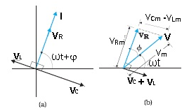
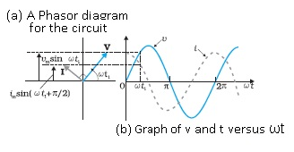
(a) Phasor diagram of V and I.
(b) Graphs of v and i versus w t for a series LCR circuit where XC > XL.
Problem:- A sinusoidal voltage of peak value 283 V and frequency 50 Hz is applied to a series LCR circuit in which R = 3 W, L = 25.48 mH, and C = 796 μF.
Find (a) the impedance of the circuit; (b) the phase difference between the voltage across the source and the current; (c) the power dissipated in the circuit; and (d) the power factor.
Answer:–
(a) To find the impedance of the circuit, we first calculate XL and XC.
XL = 2 π ν L
= 2 × 3.14 × 50 × 25.48 × 10–3 W = 8 W
XC = (1/2 π ν C)
= (1/ 2 × 3.14 × 50 × 796 x 10-6)
= 4Ω
Therefore,
Z = √R2 + (XL − XC )2 =√(3)2 + (8 − 4)2
= 5 Ω
(b) Phase difference, f = tan–1 ϕ (XC – XL)/(R)
=tan-1 ((4-8)/(3))
=-53.10
Since ϕ is negative, the current in the circuit lags the voltage across the source.
(c) The power dissipated in the circuit is
P2 = I R
Now, I = (IM)/(√2)
=(1/√2 )(283/5)
=40 A
Therefore, P = (40A )2× 3W = 4800
(d) Power factor = cos ϕ = cos53.1° = 0.6
Resonance
- Resonance is defined as the tendency of the system to oscillate at greater amplitude at some frequencies than at others.
- It is common among the systems that have a tendency to oscillate at a particular frequency and that frequency is known as natural frequency.
- It is common among the systems which have the tendency to oscillate at a particular frequency.
Examples:-
- A pendulum oscillates at its natural frequency. If a push is given to pendulum its amplitude increases. This frequency with which pendulum oscillates with a greater amplitude is known as the resonance frequency.
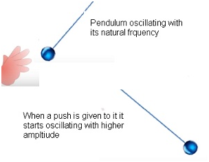
- Swing. A child when sitting on a swing, he swings at his natural frequency. But if someone gives a push to the swing from the behind at the same frequency with which the swing was swinging earlier. Then the amplitude increases ,this is known as resonance and frequency is known as resonant frequency.
Problem:- Obtain the resonant frequency ωr of a series LCR circuit with L = 2.0 H, C = 32 μF and R = 10 Ω. What is the Q-value of this circuit?
Answer:-
Inductance, L = 2.0 H
Capacitance, C = 32 μF = 32 × 10−6 F
Resistance, R = 10 Ω
Resonant frequency is given by the relation,
ωr =(1√LC)
=(1/√2 × 32 × 10−6)
=1/(8 × 10−3) = 125 rad/s.
Now, Q-value of the circuit is given as:
Q = (1/R)√(L/C)
=(1/10)√(2)/(32 × 10−6)
=1/(10 × 4 × 10−3) = 25
Hence, the Q-Value of this circuit is 25.
Resonance of Series LCR circuit
- At resonant frequency: Amplitude is maximum.
- In LCR circuit, current amplitude is given as:- Im = (Vm/Z).
- => Im = (Vm/√( R2 + (XC – XL)2)
- At resonance ,Im = max => Z = minimum when (XC – XL) =0 => XC = XL
- =>(1/ωC) = ωL => ω =(1/√LC).
- This value is known as resonant frequency ω0 =(1/√LC) .
- From the graph we can see that the value of Im increases with the value of ω, it reaches a maximum value which is ω0 and then again it decreases.
Important Note: –
- Resonance is exhibited by a circuit only if both L and C are present in the circuit.
- Only then the voltages across L and C cancel each other (as both being out of phase) and the current amplitude is (Vm/R), the total source voltage appearing across R. This means that we cannot have resonance in a RL or RC
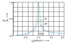
The above graph shows the variation of im with w for two cases:
(i) R = 100 W, (ii) R = 200 W, L = 1.00 mH.
Problem:- A series LCR circuit with R = 20 Ω, L = 1.5 H and C = 35 μF is connected to a variable frequency 200 V ac supply. When the frequency of the supply equals the natural frequency of the circuit, what is the average power transferred to the circuit in one complete cycle?
Answer:- At resonance, the frequency of the supply power equals the natural frequency of the given LCR circuit.
Resistance, R = 20 Ω
Inductance, L = 1.5 H
Capacitance, C = 35 μF = 30 × 10−6 F
AC supply voltage to the LCR circuit, V = 200 V
Impedance of the circuit is given by the relation,
Z = √R2 + (XL − XC)2
At resonance, XL = XC
∴ Z = R = 20 Ω
Current in the circuit can be calculated as:
I = (V/Z)
=(200/20) = 10 A
Hence, the average power transferred to the circuit in one complete cycle:
VI = 200 × 10 = 2000 W.
Applications of Resonance
Resonance circuits have variety of applications. They are as following:-
Tuning circuit of radio or TV set:-
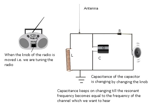
- Inside radio there is a circuit known as tuner circuit. This tuner circuit is LCR circuit.
- Every radio has an antenna which receives signals from multiple stations.
- When we are tuning the knob of the radio to connect to particular station we are changing the capacitance of the capacitor in the circuit.
- As capacitance is changing the resistance also changes and when the natural frequency matches with the resonant frequency then the amplitude will attain the maximum value.
- As a result we will be able to hear song.
- When the amplitude is minimum we won’t be able to hear any song and when amplitude is near to maximum value we will be able to hear the song but the clarity won’t be very clear.
Problem:– A radio can tune over the frequency range of a portion of MW broadcast band: (800 kHz to 1200 kHz). If its LC circuit has an effective inductance of 200 μH, what must be the range of its variable capacitor?
Answer:-
The range of frequency (ν) of a radio is 800 kHz to 1200 kHz.
Lower tuning frequency, ν1 = 800 kHz = 800 × 103 Hz
Upper tuning frequency, ν2 = 1200 kHz = 1200 × 103 Hz
Effective inductance of circuit L = 200 μH = 200 × 10−6 H
Capacitance of variable capacitor for ν1 is given as:
C1 = (1/ω12L)
Where,
ω1 = Angular frequency for capacitor C1
= 2πν1
= 2π × 800 × 103 rad/s
∴ C1 = (1/ (2π × 800 × 103)2 × 200 × 10−6)
= 1.9809 × 10⁻¹⁰ F = 198 pF
Capacitance of variable capacitor for ν2 is given as:
C2 = (1/ω22L)
Where,
ω2 = Angular frequency for capacitor C2
= 2πν2
= 2π × 1200 × 103 rad/s
∴ C2 = (1/(2π × 1200 × 103)2 × 200 × 10−6
= 0.8804 × 10⁻¹⁰ F = 88 pF
Hence, the range of the variable capacitor is from 88.04 pF to 198.1 pF.
Problem:-
The given Figure shows a series LCR circuit connected to a variable frequency 230 V source. L = 5.0 H, C = 80μF, R = 40 Ω
(a) Determine the source frequency which drives the circuit in resonance.
(b) Obtain the impedance of the circuit and the amplitude of current at the resonating frequency.
(c) Determine the rms potential drops across the three elements of the circuit. Show that the potential drop across the LC combination is zero at the resonating frequency.
Answer:-
Inductance of the inductor, L = 5.0 H
Capacitance of the capacitor, C = 80 μH = 80 × 10−6 F
Resistance of the resistor, R = 40 Ω
Potential of the variable voltage source, V = 230 V
(a) Resonance angular frequency is given as:
ωr = 1/√LC
=1/√(5 × 80 × 10−6)
= (103/20) = 50 rad/s
Hence, the circuit will come in resonance for a source frequency of 50 rad/s.
(b) Impedance of the circuit is given by the relation:
Z = √R2 + (XL − XC)2
At resonance, XL = XC ⇒ Z = R = 40 Ω
Amplitude of the current at the resonating frequency is given as:
Io = (Vo/Z)
Where,
Vo = Peak voltage = √2 V
∴ Io = √2 V/(Z)
= (√2 × 230)/40 = 8.13 A
Hence, at resonance, the impedance of the circuit is 40 Ω and the amplitude of the current is 8.13 A.
(c) RMS potential drop across the inductor,
(VL)rms = I × ωrL
Where,
Irms = (Io /√2)
= (√2 V)/(√2 Z)
= (230/40) = (23/4)A
∴ (VL)RMS = (23/4) x(50×5)
= 1437.5 V
Potential drop across the capacitor:
∴ (VC)RMS = I × (1/ωrC)
=(23/4)×(1/50 × 80 × 10−6) = 1437.5 V
Potential drop across the resistor:
(VR)RMS = IR = (23/4) × 40 = 230 V
Potential drop across the LC combination:
VLC = I(XL − XC)
At resonance, XL = XC ⇒ VLC = 0
Hence, it is proved that the potential drop across the LC combination is zero at resonating frequency.
Power associated with AC circuit
Consider source voltage V = Vm sinωt ,
- I = Im Vm sin( ωt + f)
where f = phase angle between current and voltage.
- Im = (Vm/Z) and f = tan-1 (XC –XL)/(R)
- Instantaneous power p = VI = Vm Im sin ωt sin(ωt + f)
- p = (Vm Im/2) [cos(-f) – cos(2 ωt + f)] [ By using 2sinA sinB = cos(A-B) cos(A+B)]
- p = (Vm Im/2) [cosf – cos(2 ωt + f)]
- Average Power P = (1/T) 0T∫ p dt
- = (1/T) 0T∫ (Vm Im/2) [cosf – cos(2 ωt + f)] dt
After Simplifying ,
- P = (Vm Im/2) cosf
- Where cosf = power factor.
Power in different AC circuits
- Resistive :-
- f = 0 because voltage and current are in phase.
- Therefore P = (Vm Im/2). There will be maximum power dissipation.
- Inductive:-
- f = (∏/2) as current lags behind the voltage by (∏/2) .
- Therefore P = 0.
- Capacitive:-
- f = (∏/2) as voltage lags behind the current by (∏/2) .
- Therefore P =0.
- LCR:-
- f = tan-1 (XC –XL)/(R)
- Power dissipates only in resistor.
- At resonance in LCR :-
- XC = XL
- Therefore f = 0.
- P = (Vm Im/2). There will be maximum power dissipation.
Problem:- A circuit containing a 80 mH inductor and a 60 μF capacitor in series is connected to a 230 V, 50 Hz supply. The resistance of the circuit is negligible.
(a) Obtain the current amplitude and rms values.
(b) Obtain the rms values of potential drops across each element.
(c) What is the average power transferred to the inductor?
(d) What is the average power transferred to the capacitor?
(e) What is the total average power absorbed by the circuit?
[‘Average’ implies ‘averaged over one cycle’.]
Answer:-
Inductance, L = 80 mH = 80 × 10−3 H
Capacitance, C = 60 μF = 60 × 10−6 F
Supply voltage, V = 230 V
Frequency, ν = 50 Hz
Angular frequency, ω = 2πν= 100 π rad/s
Peak voltage, V0 = V √2
(a) Maximum current is given as:
Hence, RMS value of current,
I0 = (V0)/( ωL – (1/ ωC))
=(230 √2)/((100 π x 80 x10-3) –(1/(100 π x60 x 10-6))
=(230 √2) / ( 8π x (1000/6 π)) =-11.63A
The negative sign appears because (ωL) < (1/ ωC).
Amplitude of maximum current, II0I =11.63A
I= (I0)/( √2)
=(-11.63)/( √2)
=-8.22A
(b) Potential difference across the inductor,
VL= I × ωL
= 8.22 × 100 π × 80 × 10−3
= 206.61 V
Potential difference across the capacitor,
VC = (I x (1/ ωC))
= (8.22) x (1/ 100 π x 60 x 10-6)
=436.3V
The negative sign appears because
Amplitude of maximum current,
(c) Average power consumed by the inductor is zero as actual voltage leads the current by π/2.
(d) Average power consumed by the capacitor is zero as voltage lags current by π/2.
(e) The total power absorbed (averaged over one cycle) is zero.
LC oscillations
- LC circuit consists of an inductor and a capacitor connected in a series.
- Consider a circuit with a capacitor and an inductor, energy taken from the cell and given to capacitor keeps oscillating between L & C.
- The oscillations between L and C are referred as LC oscillations.
- When AC voltage is applied to the capacitor, it will first charge and then will discharge ,again will charge and discharge and this process will keep on continuing.
- When the capacitor is fully charged it will start discharging and the charge is transferred to the inductor which is connected to the capacitor.
- Because of change in the current there will be change in the magnetic flux of the inductor in the circuit.
- As a result there will be an emf induced in the inductor.
- The EMF is given by e = – L (dI/dt). The self-induced emf will try to oppose the growth of the current.
- As a result when the capacitor gets completely discharged all the energy stored in the capacitor will now be stored in the inductor.
- The capacitor will become fully discharged whereas inductor will be storing all the energy.
- As a result now the inductor will start charging the capacitor. The energy stored in the capacitor will start again increasing .
- This cycle will keep on continuing.
- These oscillations are known as LC oscillations. Electric field energy and magnetic field energy will keep oscillating.
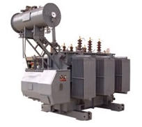
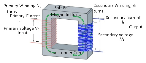
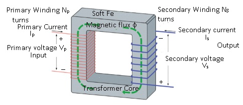
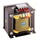
Transformers
- A transformer is a device that changes voltage from one value to another.
- Power at the input end is equal to the power at the output end.
- Only the voltage will increase or decrease.
Alternating Transformer
Principle:-
Transformers work on the principle of Mutual induction.
Mutual Induction :- Suppose there are 2 inductors if some current flows through coil(1) ,there will be change in the current as a result there will be change in the magnetic flux, as a result there will be change in the magnetic flux in the coil (2) and because of which emf is induced in the coil(2).
Construction:-
A Transformer consists of :-
- Primary coil:-
- Primary coil has ‘n’ number of turns of wire over a piece of soft iron core.
- It is the input end.
- Secondary coil :-
- Secondary coil has ‘n’ number of turns of any wire(like copper etc.) .
- It is the output end as we receive output from this end.
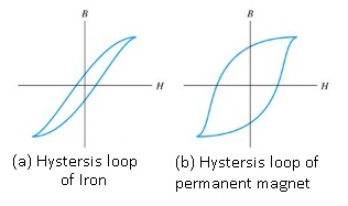
- Soft iron core :-
- The hysteresis curve for iron is extremely thin because of which it covers minimum possible area.
- As the area of the hysteresis loop of iron is very less therefore the energy lost by the transformer will be very less.
- Permanent magnet is not suitable to use in transformers because the energy lost will be huge.
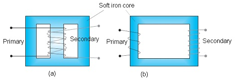
Two arrangements for winding of primary and secondary coil in a transformer:
(a) two coils on top of each other, (b) two coils on separate limbs of the core.
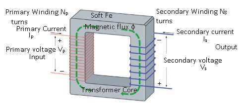
Working :-
- An input voltage(AC source) is applied across the primary coil. As a result alternating current is produced in the primary coil.
- The alternating current will give rise to alternating flux is produced in the coils.
- Because of change in the magnetic flux emf will be induced .
- There will be 2 Emfs produced in the circuit. 1. Self –induction 2. Mutual induction.
- There will be self – induced emf in the primary coil , because of change in the magnetic flux in the primary coil there will be corresponding change in the magnetic flux associated with the secondary coil which will give rise to induced emf in the secondary coil.
- Mutual induction takes place in the secondary coil.
- Induced emf in the primary coil = ep = -Np (df/dt)
- Where (df/dt) = rate of change magnetic flux and Np = number of turns in the primary coil.
- Mutual induction in the secondary coil es = – Ns (df/dt)
- Where Ns = number of turns in the secondary coil.
- Assuming resistance =0 in both primary and secondary coils.
- Therefore ep = Vp (Voltage across primary coil)
- Vp = -Np (df/dt) (equation(1)) and
- es = Vs (Voltage across secondary coil) = – Ns (df/dt) (equation(2))
- Dividing equation(1) with (2):-
- (Vp/Vs) = (Np/ Ns)
- => Vs = (Ns/ Np) Vp
- (Vp/Vs) = (Np/ Ns)
- Power at the input end is same as the power at the output end.
- Therefore Pintput = Poutput
- => IpVp = IsVs
Types of Transformers
There are 2 types of transformers:-
Step up transformer:-
- This transformer amplifies the voltage. The output is higher than the input which is being supplied.
- This condition will be true Vs > Vp only when Ns > Np and Ip < Is.
- Vs = (Ns/ Np) Vp
- The output of the transformer à voltage will be high and current will be less.
- They are used in the power stations which supply power to the houses.
Step down transformer:-
- For Vs < Vp to be true then Ns < Np .
- Is > Ip so that (Pintput = Poutput).
- Output is low voltage and high current.
- This transformer is used in welding
Problem:- A power transmission line feeds input power at 2300V to a step down transformer with its primary windings having 4000 turns. What should be the number of turns in the secondary in order to get output power at 230V?
Answer:-
Input voltage , Vp = 2300V
Number of turns in primary coil, Np =4000
Output voltage, Vs = 230V
Number of turns in secondary coil, Ns
Using (Vp/Vs) = (Np/ Ns)
(2300/230) = (4000/ Ns)
Ns = (4000 x 230)/(2300)
Ns =400
Hence there are 400 turns in the secondary coil.
Problem:- At a hydroelectric power plant, the water pressure head is at a height of 300m and the water flow available is 100 m3 s−1. If the turbine generator efficiency is 60%, estimate the electric power available from the plant (g =9.8 m s−2 ).
Answer:-
Height of water pressure head, h = 300 m
Volume of water flow per second, V = 100 m3/s
Efficiency of turbine generator, n = 60% = 0.6
Acceleration due to gravity, g = 9.8 m/s2
Density of water, ρ = 103 kg/m3
Electric power available from the plant = η × hρgV
= 0.6 × 300 × 103 × 9.8 × 100
= 176.4 × 10⁶ W
= 176.4 MW
Applications of Transformers
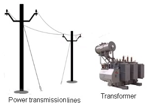
Transmission of power over long distances :-
- Suppose there is a main power station, from there power is send to different sub area power stations and from there it is supplied to different houses.
- At the main power station there is step-up transformer, it will amplify the voltage and current is reduced.
- When the current is reduced therefore heating will be reduced to a great extent.
- The power loss is minimized to a great extent till it reaches the area sub stations.
- At the area substation step-down transformer is used. This transformer will reduce the voltage and then supplied to the houses.
- The line power loss will be not very much as the distance between the houses and area power substation won’t be very large.
Transformers are used to regulate the voltage. Many appliances use voltage stabilizers which regulate the voltage so that the electronic devices are not harmed when there is fluctuation in the voltage.

Energy losses in actual transformers
Flux leakage:-
- There are air gaps between the primary and the secondary coils because of which the change of flux which is associated with the primary coil is not completely transferred to secondary coil.
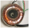
- In order to reduce the loss secondary coil can be wound over the primary coil.
- For example:- In case of toroidal transformer cores, over the primary coil secondary coil is wound above it. As a result there is no air gap in between them.
Resistance of windings:-
- The wire used for the windings has some resistance and so, energy is lost due to heat produced in the wire (I2R).
- If the area of the cross section of the wire is increased then the resistance will be reduced considerably.
- So the thick wires are used in the windings of primary and secondary coils as a result resistance will be less .
- The amount of heat lost because of wires will be less as resistance is minimal.
Eddy currents:-
- Soft Iron core also gets heated up because of magnetic flux as a result eddy currents are developed in the soft iron core.
- Core gets heated up because of eddy currents. This will harm the transformer core.
- In order to prevent this laminated core can be used. Because of insulated covering eddy currents are not able to produce the heating effects.
Hysteresis:-
- There is energy loss involved during the magnetisation of the material of the core.
- Always those materials are to be chosen for which hysteresis loss is minimum.
- That is why Soft Iron core is used instead of permanent magnets.
Problem:- A small town with a demand of 800 kW of electric power at 220 V is situated 15 km away from an electric plant generating power at 440 V. The resistance of the two wire line carrying power is 0.5 Ω per km. The town gets power from the line through a 4000 – 220 V step-down transformers at a sub-station in the town.
(a) Estimate the line power loss in the form of heat.
(b) How much power must the plant supply, assuming there is negligible power loss due to leakage?
(c) Characterise the step up transformer at the plant.
Answer:-
Total electric power required, P = 800 kW = 800 × 103 W
Supply voltage, V = 220 V
Voltage at which electric plant is generating power, V’ = 440 V
Distance between the town and power generating station, d = 15 km
Resistance of the two wire lines carrying power = 0.5 Ω/km
Total resistance of the wires, R = (15 + 15)0.5 = 15 Ω
A step-down transformer of rating 4000 − 220 V is used in the sub-station.
Input voltage, V1 = 4000 V
Output voltage, V2 = 220 V
RMS current in the wire lines is given as:
I = (P/V1)
= (800 x 103) / (4000)
I = 200A
(a) Line power loss = I2R
= (200)2× 15
= 600 × 103 W
= 600 kW
(b) Assuming that the power loss is negligible due to the leakage of the current:
Total power supplied by the plant = 800 kW + 600 kW
= 1400 kW
(c) Voltage drop in the power line = IR = 200 × 15 = 3000 V
Hence, total voltage transmitted from the plant = 3000 + 4000
= 7000 V
Also, the power generated is 440 V.
Hence, the rating of the step-up transformer situated at the power plant is
440 V − 7000 V.
Problem:- Do the same exercise as above with the replacement of the earlier transformer by a 40,000-220 V step-down transformer (Neglect, as before, leakage losses though this may not be a good assumption any longer because of the very high voltage transmission involved). Hence, explain why high voltage transmission is preferred?
Answer:-
The rating of a step-down transformer is 40000 V−220 V.
Input voltage, V1 = 40000 V
Output voltage, V2 = 220 V
Total electric power required, P = 800 kW = 800 × 103 W
Source potential, V = 220 V
Voltage at which the electric plant generates power, V’ = 440 V
Distance between the town and power generating station, d = 15 km
Resistance of the two wire lines carrying power = 0.5 Ω/km
Total resistance of the wire lines, R = (15 + 15)0.5 = 15 Ω
P = V1I
RMS current in the wire line is given as:
I = (P/V1)
= (8000 x 103) / (40000)
=20 A
(a) Line power loss = I2R
= (20)2 × 15
= 6 kW
(b) Assuming that the power loss is negligible due to the leakage of current.
Hence, power supplied by the plant = 800 kW + 6kW = 806 kW
(c) Voltage drop in the power line = IR = 20 × 15 = 300 V
Hence, voltage that is transmitted by the power plant = 300 + 40000 = 40300 V
The power is being generated in the plant at 440 V.
Hence, the rating of the step-up transformer needed at the plant is 440 V − 40300 V.
Hence, power loss during transmission = (600/1400) x 100% = 42.8%
In the previous exercise, the power loss due to the same reason is:-
(6/806) x 100 = 0.744%
Since the power loss is less for a high voltage transmission, high voltage transmissions are preferred for this purpose.
Chapter-7-Alternating-CurrentNCERT Exercises ( Alternating Current )
Question 1.
A 100 Q resistor is connected to a 220 V, 50 Hz a.c. supply.
(a) What is the rms value of current in the circuit?
(b) What is the net power consumed over a full cycle?
Solution:
(a) Here virtual a.c. voltage is 220 V at a frequency of 50 Hz. So, rms value of current
(b) Power in complete cycle
Question 2.
(a) The peak voltage of an a.c. supply is 300 V. What is the rms voltage?
(b) The rms value of current in an a.c. circuit is 10 A. What is the peak current?
Solution:
(a) The peak value of a.c. supply is given 300 V.
Question 3.
A 44 mH inductor is connected to 220 V, 50 Hz ac supply. Determine the rms value of current in the circuit.
Solution:
Question 4.
A 60 μF capacitor is connected to a 110 V, 60 Hz a.c. supply. Determine the rms value of current in the circuit.
Solution:
Question 5.
In previous questions 3 and 4, what is the net power absorbed by each circuit over a complete cycle. Explain your answer.
Solution:
For question 3, Power in the circuit with pure inductor P = Eυlυ cos π/2 = 0. For question 4, Power in complete cycle P = Eυlυ cos (-π/2) = 0.
Question 6.
Obtain the resonant frequency a), of a series LCR circuit with L = 2.0 H, C = 32 μF and R = 10 Ω2. What is the Q-value of this circuit?
Solution:
Resonant angular frequency in series LCR circuit
Question 7.
A charged 30 pF capacitor is connected to a 27 mH inductor. What is the angular frequency of free oscillations of the circuit?
Solution:
Angular frequency of LC oscillations
Question 8.
Suppose the initial charge on the capacitor given in question 7 is 6 mC. What is the total energy stored in the circuit initially? What is the total energy at later time?
Solution:
Initial energy on capacitor
Any time total energy in the circuit is constant, hence energy later is 0.6 J.
Question 9.
A series LCR circuit with R = 20 Ω 2, L = 1.5 H and C = 35 μF is connected to a variable-frequency 200 V ac supply. When the frequency of the supply equals the natural frequency of the circuit, what is the average power transferred to the circuit in one complete cycle?
Solution:
Average power transferred to the circuit in one complete cycle at resonance
Question 10.
A radio can tune over the frequency range of a portion of MW broadcast band: (800 kHz to 1200 kHz), if its LC circuit has an effective inductance of 200 μH, what must be the range of its variable capacitor?
Solution:
For tuning, the natural frequency i.e., the frequency of L-C oscillations should be equal to frequency of radio waves received by the antenna in the form of same frequency current in the L-C circuit. For tuning at 800 kHz, required capacitance
So, the variable capacitor should have a frequency range between 87.9 pF to 197.8 pF.
Question 11.
Figure shows a series LCR circuit connected to a variable frequency 230 V source. L = 5.0 H. C = 80 μF, ft = 40 Q
(a) Determine the source frequency which drives the circuit in resonance.
(b) Obtain the impedance of the circuit and the amplitude of current at the resonating frequency.
(c) Determine the rms potential drops across -the three elements of the circuit. Show that the potential drop across the LC combination is zero at the resonating
Solution:
(a) Condition for resonance is when applied frequency matches with natural frequency.
(b) At resonance, impedance Z = R
(c) Potential drop across ‘L’
Question 12.
An LC circuit contains a 20 mH inductor and a 50 μF capacitor with initial charge of 10 mC. The resistance of the circuit in negligible. Let the instant the circuit is closed be t = 0.
(a) What is the total energy stored initially? Is it conserved during LC oscillations?
(b) What is the natural frequency of the circuit?
(c) At what time is the energy stored
- completely electrical (i.e., stored in the capacitor)?
- completely magnetic (i.e., stored in the inductor)?
(d) At what times is the total energy shared equally between the inductor and capacitor?
(e) If a resistor is inserted in the circuit, how much energy is eventually dissipated as heat?
Solution:
(a) Total energy is initially in the form of electric field within the plates of charged capacitor.
If we neglect the losses due to resistance of connecting wires, the total energy remain consumed during LC oscillations.
(b) Natural frequency of the circuit
(c) Instantaneous electrical energy
(d) timings for energy shared equally between inductor and capacitor.
(e) When a resistor is inserted in the circuit, eventually all the energy will be lost as heat across resistance. The oscillation will be damped.
Question 13.
A coil of inductance 0.50 H and resistance 100 Ω2 is connected to a 240 V. 50 Hz ac supply.
(a) What is the maximum current in the coil?
(b) What is the time lag between the voltage maximum and the current maximum?
Solution:
(a) Virtual current in the coil
(b)
Question 14.
Obtain the answers (a) and (b) in Q. 13, if the circuit is connected to a high frequency supply (240 V, 10 kHz). Hence, explain the statement that at very high frequency, an inductor in a circuit nearly amounts to an open circuit. How does an inductor behave in a dc circuit after the steady state?
Solution:
At very high frequency, XL increases to infinitely large, hence circuit behaves as open circuit.
(a) Current in the coil, lrms =
This current is extremely small. Thus, at high frequencies, the inductive reactance of an inductor is so large that it behaves as an open circuit.
(b)
In dc circuit (after steady state), v = 0 and as such XL = 0. In this case, the inductor behaves like a pure resistor as it has no inductive reactance.

Question 15.
A 100 μF capacitor in series with a 40 Q resistance is connected to a 110 V, 60 Hz supply.
(a) What is the maximum current in the circuit?
(b) What is the time lag between the current maximum and the voltage maximum?
Solution:
(a) Virtual current in the coil
(b)
Question 16.
Obtain the answer to (a) and (b) in Q.15 if the circuit is connected to a 110 V, 12 kHz supply? Hence, explain the statement that a capacitor is a conductor at very high frequencies. Compare this behaviour with that of a capacitor in a dc circuit after the steady state.
Solution:
Given,
(a)
This value of current is same as that without capacitor in the circuit. So, at high frequency, a capacitor offer negligible resistance (0.1326 Ω in this case), it behave like a conductor.
(b)
In dc circuit, after steady state, v = 0 and accordingly, XC = ∞, i.e., a capacitor amounts to an open circuit, i.e., it is a perfect insulator of current.
Question 17.
Keeping the source frequency equal to the resonating frequency of the series LCR circuit, if the three elements, L, C and R are arranged in parallel, show that the total current in the parallel LCR circuit is minimum at this frequency. Obtain the current rms value in each branch of the circuit for the elements of frequency. Source has emf 230 V and L = 5.0 H, C = 80 μF, ff = 40 Ω2.
Solution:
impedance of R and X in parallel is given by
Thus, impedance Z = R and will be maximum. Hence, in parallel resonant circuit, current is minimum at resonant frequency. Current through circuit elements
Since, IL and IC are opposite in phase, so net current,
Question 18.
A circuit containing a 80 mH inductor and a 60 μF capacitor in series is connected to a 230 V, 50 Hz supply. The resistance of the circuit is negligible.
(a) Obtain the current amplitude and rms values.
(b) Obtain the rms values of potential drops across each element.
(c) What is the average power transferred to the inductor?
(d) What is the average power transferred to the capacitor.
(e) What is the total average power absorbed by the circuit? [‘Average’implies’averaged over one cycle’.
Solution:
(a) Inductive reactance , XL = 2πƒL
(b) Potential drop across L, VL = lυXL X
(c) Average power transferred to inductor is zero, because of phase difference π/2
(d) Average power transferred to capacitor is also zero, because of phase difference π/2
(e) total power absorbed by the circuit
Question 19.
Suppose the circuit in Q. 18 has a resistance of 15 Ω2. Obtain the average power transferred to each element of the circuit and the total power absorbed.
Solution:
If the circuit has a resistance of 15 Ω2, now it is LCR series resonant circuit.
Question 20.
A series LCR circuit with L = 0.12 H, C = 480 μF, R = 23 Ω2 is connected to a 230 V variable frequency supply.
(a) What is the source frequency for which current amplitude is maximum. Obtain this maximum value.
(b) What is the source frequency for which average power absorbed by the circuit is maximum. Obtain the value of this maximum power.
(c) For which frequencies of the source is the power transferred to the circuit half the power at resonant frequency? What is the current amplitude at these frequencies?
(d) What is the Q-factor of the given circuit?
Solution:
(a) At resonant frequency, the current amplitude is maximum.
(b) Maximum power loss at resonant frequency, P = Eυlυ cos θ
(c) Let at an angular frequency, the source power is half the power at resonant frequency.
Question 21.
Obtain the resonant frequency and Q-factor of a series LCR circuit with L = 3.0 H, C= 27 μF, and R = 7.4 fl. It is desired to improve the sharpness of the resonance of the circuit by reducing its ‘full width at half maximum’ by a factor of 2. Suggest a suitable way.
Solution:
we want to improve the quality factor to twice, without changing resonant frequency (without changing L and C).
Question 22.
Answer the following questions.
(a) In any ac circuit, is the applied instantaneous voltage equal to the algebraic sum of the instantaneous voltages across the series elements of the circuit? Is the same true for rms voltage?
(b) A capacitor is used in the primary circuit of an induction coil.
(c) An applied voltage signal consists of a superposition of a dc voltage and an ac voltage of high frequency. The circuit consists of an inductor and a capacitor in series. Show that the dc signal will appear across Cand the ac signal across L.
(d) A choke coil in series with a lamp is connected to a dc line. The lamp is seen to shine brightly. Insertion of an iron core in the choke causes no change in the lamp’s brightness. Predict the corresponding observations if the connection is to an ac line.
(e) Why is choke coil needed in the use of fluorescent tubes with ac mains? Why can we not use an ordinary resistor instead of the choke coil?
Solution:
(a) It is true that applied instantaneous voltage is equal to algebraic sum of instantaneous potential drop across each circuit element is series.
But the rms voltage applied is equal to vector sum of potential drop across each element, as voltage drops are in different phases.
(b) At the time of broken circuit of the induction coil, the induced high voltage charges the capacitor. This avoid sparking in the circuit.
(c) Inductive reactance, XL = 2πƒL For a.c., Xc α ƒ
So, superimpose applied voltage will have all d.c. potential drop across Xc and will have most of a.c potential drop across XL.
(d) Inductor offer no hinderance to d.c. XL = 0, so insertion of iron core does not effect the d.c. current or brightness of lamp connected. But it definitely effect a.c. current as insertion of iron core increases L = μm nl thus increases XL (2πƒL). A.c. current in the E circuit reduces IP = 
(e) A fluorescent tube is connected directly across a 220 V source, it would draw large current which may damage the filaments of the tube. So a choke coil which behaves as L-R circuit reduces the current to appropriate value, and that also with a lesser power loss.
An ordinary esistor used to control the current would have maximum power wastage as heat.
Question 23.
A power transmission line feeds input power at 2300 V to a step down transformer with its primary windings having 4000 turns. What should be the number of turns in the secondary in order to get output power at 230 V?
Solution:
Question 24.
At a hydroelectric power plant, the water pressure head is at a height of 300 m and the water flow available is 100 m3s-1. If the turbine generator efficiency is 60%, estimate the electric power available from the plant (g = 9.8 ms-2).
Solution:
Work done by liquid pressure = pressure x volume shifted power of flowing water
Question 25.
A small town with a demand of 800 kW of 1 electric power at 220 V is situated 15 km away from an electric plant generating power at 440V. The resistance of the two wire line carrying power is 0.5 Q per km. The town gets 1 power from the line through a 4000-220 V step- down transformer at a sub station in the town.
(a) Estimate the line power loss in the form of heat.
(b) How much power must the plant supply, assuming there is negligible power loss due to leakage?
(c) Characterize the step up transformer at the plant.
Solution:
(a) Line power loss,
(b) Assuming no power loss due to leakage, total power need to be supply by the power plant
(c) Potential drop in the line,
Question 26.
Repeat the same exercise as in the previous question with the replacement of the earlier transformer by a 40,000-220 V step down transformer. (Neglect, as before, leakage losses through this may not be a good assumption any longer because of the very high voltage transmission involved). Hence, explain why high voltage transmission is preferred?
Solution:
(a) Line power loss,
(b) Power supplied by the plant
(c) Voltage drop in the line,
So, by supply of electricity at higher voltage, 40,000 V instead by 4000 V the power loss is reduced greatly that is why the electric power is always transmitted at very high voltage.
Mohd. Sharif Qualification: B.Tech (Mechanical Engineering) [Founder of Wisdom Academy] [Aim Foundation & Free-Education.In] [Engineer By Profession | Teacher By Choice] [Blogger, YouTube Creator]