-

- 0 Comments
( Electromagnetic Induction notes) www.free-education.in is a platform where you can get pdf notes from 6th to 12th class notes, General Knowledge post, Engineering post, Career Guidelines , English Speaking Trick , How to crack interview and lots more.
Class 12th Physics Chapter 6 Electro Magnetic Induction Notes
Introduction ( Electromagnetic Induction )
- The phenomenon in which electric current is generated by varying magnetic fields is appropriately called electromagnetic induction.
- Electromagnetic induction is very cost-effective.
- Wireless charging phenomenon is possible due to electromagnetic induction.
- Electromagnetic Induction name suggests it is related with electricity,magnetism and induction.
- Induction means to induce something or to generate something.
- Therefore electromagnetic induction means induction of electric current due to magnetic field.
- We will see how the experiments performed by Faraday and Henry led to the development of modern day generators and transformers.
- We will also study that the magnetic field is capable of producing current in the conductor.
Examples
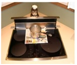
- Pan getting heated up without burning the paper. Heat which is getting transferred is due to induced current. More the amount of current induced, more is the amount of heat dissipated.
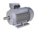
By Changing the orientation of coil wrt the magnetic fields able to induced current in generators or motors
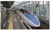
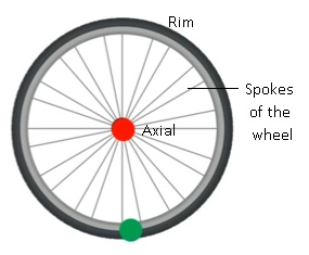
Eddy current acting on the wheel of the train
Torch not using cell: It has solenoid where current can be induced by the change in magnetic field as there is a magnet inside it

Magnetic Flux
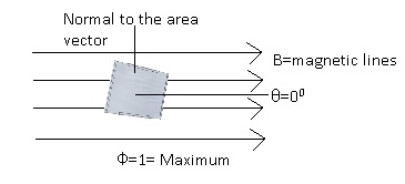
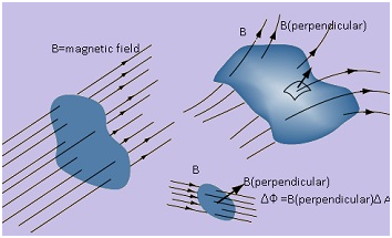
- Magnetic flux is defined as the product of the average magnetic field times the perpendicular area it penetrates.
- In case of magnetic flux orientation of the area vector is considered.
- Area vector is considered as the amount of lines crossing an area also varies with the orientation of the area.
- It is a scalar quantity.
- Magnetic flux is denoted by ΦB or Φ.
- I Unit- Weber (Wb).
- Where 1Wb= 1Tesla x 1m2 (S.I. unit of B = Tesla and Area=m2)
- G.S unit-Maxwell (Mx).Relationship between Weber and Maxwell is;1Wb=108Mx
- Mathematically:
- ΦB = A
- B=magnetic field vector, A= area vector
- Area vector =In case of magnetic flux the amount of lines crossing an area varies with the orientation of the area.
- ΦB = BA cos θ
- Where θ=angle between magnetic field and area vector.
- Direction of area vector is determined by the normal to the area vector.
Case 1: When the angle between the area vector and the magnetic field (θ)= 900.
- Therefore, ΦB = 0 as cos900 =0.
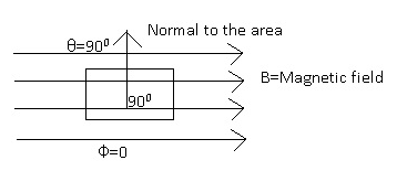
Case 2: When the angle between the area vector and the magnetic field (θ)= 00.
- Therefore,ΦB = BA as cos 0=1.
Faraday’s Experiment 1
- One of the scientists Faraday performed series of experiments and based on the results he gave law on induction.
- He introduced the phenomenon of electromagnetic induction.
- Induction means to induce or to generate something.
- Electromagnetic Induction means production of electric current due to magnetic field.
- Magnetic field is capable of producing current in a conductor.
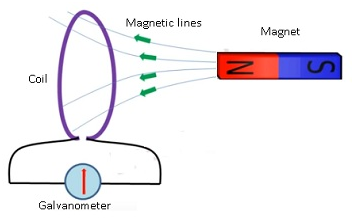
Michael Faraday
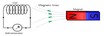
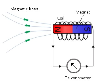
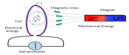
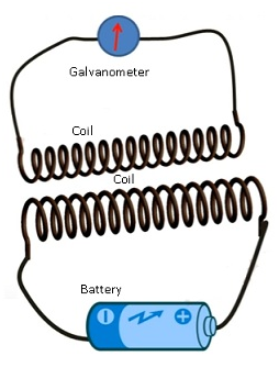
- Faraday took a coil and attached a galvanometer to it.
- As there is no battery attached therefore there is no source of current.
- He brought the magnet near the coil.
- When the magnet is moved towards the coil galvanometer showed deflection.
- Galvanometer even showed the deflection in the opposite direction when the magnet is taken away from the coil.
- When magnet was not moved there was no deflection in the galvanometer.
- This show current is related to magnet.
- Faster the magnet is moved the more is the deflection in the galvanometer.This showed more and more current flows if the magnet is moved very fast.
- Same effect was observed if the coil is moved and the magnet was not moved.
Observation:-
- Relative motion between magnet and coil induced electric current in the coil.
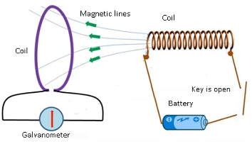
Faraday’s Experiment 2
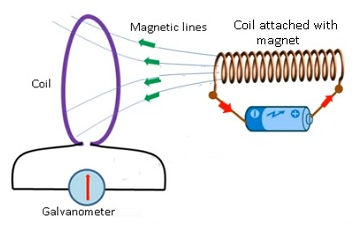
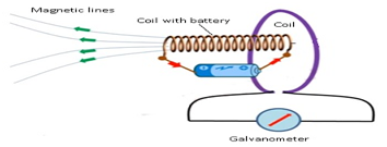
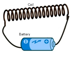
- Faraday took a coil but instead of taking magnet he took another coil which was connected to the battery.
- When the coil attached with battery was brought nearanothercoil,the galvanometer showed the deflection.
- The same phenomenon repeated even when there was no magnet.
- This shows current flowing in one coil was able to induce current in another coil.
Observation:-
- Relative motion between coils induces the electric current.
Faraday’s Experiment 3
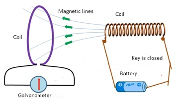
- In this experiment he wanted to prove whether the relative motion between the 2 coils is essential for the induction of current.
- In this case he took a coil, one more coil attached with a battery.
- When the circuit was open there was no current flowing through the coil.
- But as soon as the circuit was switched on there was deflection in the galvanometer.
- When the circuit was on continuously for longer period of time there was no current.
- When the circuit is switched off there was a deflection in the galvanometer in the opposite direction.
- And if the circuit is switched off for long time there was no deflection in the galvanometer.
- He observed that the galvanometer showed momentarily deflection only when the system was undergoing a change.
Observation:-
- Relative motion is not an absolute requirement for inducing current.
- There was induced current only when there is change in the system.
- Based on these 3 experiments Faraday gave 3 laws of Induction.
Faraday’s laws of Induction
First law: –
- According to the first law an emf is induced in the circuit whenever the amount of magnetic flux linked with a circuit changes.
- Current was induced because of magnetic flux, as there is some current in the circuit therefore there will be some emf flowing in the circuit.
- Whenever the amount of magnetic flux linked with the circuit changes only at that time emf is induced.
- The induced emf will be there till there is change in the flux.
- When the magnet was moved then only there was change in the flux.
- As the magnet is moving the number of magnetic lines crossing the area is also changing.
- There is a change in the flux therefore there is induced emf.
- If the magnet is not moving, there will be no change in the amount of magnetic flux so there is no induced current.
Second law: –
- According to the second law the magnitude of the induced emf in a circuit is equal to the time rate of change of magnetic flux through the circuit.
- Emf which is induced will depend upon rate at which the magnetic flux is changing.
- Mathematically:-
- Let Φ1 = flux at initial time t=0.
- Φ2 = flux after time t.
- Rate of change of flux=(Φ2 – Φ1)/t =dΦ/dt
- According to Faraday’s law:-
- Induced emf e ∝ (dΦ/dt)
- Experimentally the constant of proportionality was found to be 1 in all cases.
- Therefore e=(dΦ/dt)
- Consider a coil which has N number of turns;Therefore
- e = N(dΦ/dt)
Problem:- A circular coil of radius 10 cm, 500 turns and resistance 2 Ω is placedwith its plane perpendicular to the horizontal component of the earth’smagnetic field. It is rotated about its vertical diameter through 180°in 0.25 s. Estimate the magnitudes of the emf and current induced inthe coil. Horizontal component of the earth’s magnetic field at theplace is 3.0 × 10⁻⁵ T.
Answer:-
Initial flux through the coil,
ΦB (initial) = BA cos θ
= 3.0 × 10⁻⁵ × (π ×10–2) × cos 0º
= 3π × 10–7 Wb
Final flux after the rotation,
ΦB (final) = 3.0 × 10⁻⁵ × (π ×10–2) × cos 180°
= –3π × 10–7 Wb
Therefore, estimated value of the induced emf is,
ε = N (ΔΦ/Δt)
= 500 × (6π × 10–7)/0.25
= 3.8 × 10⁻³ V
I = ε/R = 1.9 × 10⁻³ A
Note that the magnitudes of ε and I are the estimated values. Theirinstantaneous values are different and depend upon the speed ofrotation at the particular instant.
Problem:- A small piece of metal wire is dragged across the gap between the pole pieces of a magnet in 0.5s.The magnetic flux between the pole pieces is known to be 8×10⁻⁴ Wb. Estimate the emf induced in the wire?
Answer:-
dΦ = 8×10⁻⁴ Wb
dt =0.5s
e= – (dΦ/dt) =- (8×10⁻⁴) / (0.5)
=-1.6×10⁻³V
Lenz’s law
- According to Lenz’s law:-The polarity of the induced emf is such that it tends to produce induced current in such a direction that it opposes the change in magnetic flux that produced it.
- The (-) ive sign in given equatione= (-) (dΦ/dt)tells about the direction.
- According to Faraday’s law whenever there is change in the magnetic flux, emf is induced, as aresult there will be induced current.
- According to Lenz’s law the direction of the induced current will be such that it opposes the change in the magnetic flux.
For example:-
- Consider a circuit where the magnetic flux is increasing, as a result flux will change and which induces the emf in the circuit, and as a result current will be induced in the circuit.
- The direction of the induced current will be such that it will oppose the cause which induced it.
- The induced current will be in such a direction that it decreases the magnetic flux.
- Note: – The induced current will try to oppose the change which is producing it.
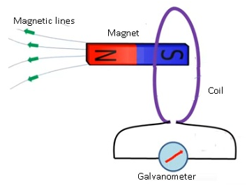
For example:-
- Consider a setup which has a coil, a magnet and a galvanometer.
- If the north pole of the magnet is brought near the coil, there will be a deflection in the galvanometer because of induced current.
- The direction of the induced current will be such that it opposes the motion of the magnet towards coil.
- Induced current will move the magnet away from the coil.
- As the north polarity of the magnet is brought near the coil as a result the induced current will be in such a direction that the face of the coil will have north polarity.
- The current will flow in the anti-clockwise direction.
- If the South Pole of the magnet was nearer to the coil then the current will flow in clockwise direction.
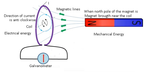
Lenz’s law: supports Conservation of energy
- Lenz’s law obeys conservation of energy.
- Magnet is moving as a result current is getting induced and when the magnet is not moving there is no induced current in the coil.
- There is a mechanical energy involved with the movement of the as magnet as a result mechanical energy is converted into electrical energy which is produced by the induced current.
- Magnetic energy used in moving magnet is getting transformed into electrical energy which is produced by the induced current.
- This shows that Lenz’s law supports conservation of energy where one form of energy is getting transformed into another form.
- Work done in moving the magnet is dissipated by Joule heating produced by the induced current.
Direction of Induced current: Lenz law
Induced current opposes CHANGE in flux.
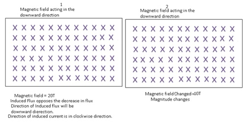
Example1: –
- Consider a region where magnetic field is acting in downward direction.
- Let magnetic field be 20T and it gets converted to 10T in the downward direction.
- As the magnetic field is changing therefore there is change in the flux which is equal to the decrease in the flux.
- As there is change in the flux there will be induced current.
- Flux of the induced current will try to oppose the decrease in the flux.
- Therefore the direction of induced flux will also be in the downward direction.
- Applying Fleming’s Right hand Thumb rule the direction of current will be given in the clockwise direction.
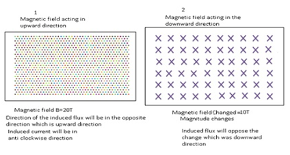
Example2:–
- Consider a magnetic field of 20T in the upward direction.If the magnetic flux is reduced to 10T in the downward direction.
- Both magnitude and the direction are changing.
- As flux is changing therefore there will be induced current.
- The direction of the induced flux will be in the opposite direction. i.e. upward direction.
- The induced flux will oppose the change which is the downward direction.
- The direction of the current will be in the anticlockwise direction.
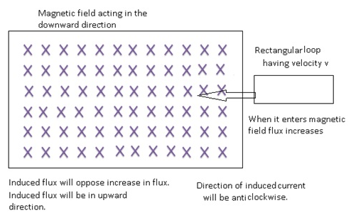
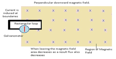
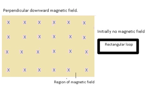
Example3:-
- Consider a region having downward magnetic field and there is a rectangular loop which is entering the region of magnetic field.
- As a result flux increases, the induced flux will oppose the increase in the flux.i.e. it will decrease the flux.
- Therefore induced flux will be in the upward direction.
- As a result the induced current will be in the anti-clockwise direction.
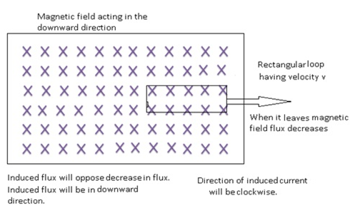
Example4:-
- Consider a region having magnetic field in the downward direction and a rectangular loop which is coming out of the magnetic field with some velocity v.
- As it is coming out therefore flux is decreasing, current will be induced because of change in flux.
- Induced flux will try to oppose the change i.e. it will try to increase the flux.
- Induced flux is in the downward direction as a result the direction of current will be clock wise.
Problem:- Use Lenz’s law to determine the direction of induced current in thesituations described by Fig.:
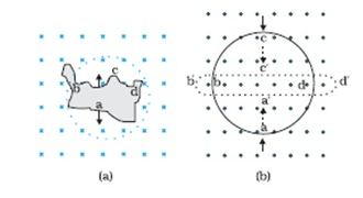
(a) A wire of irregular shape turning into a circular shape;
(b) A circular loop being deformed into a narrow straight wire.
Answer:- According to Lenz’s law, the direction of the induced Emf is such that it tends to produce a current that opposes the change in the magnetic flux that produced it.
(a) When the shape of the wire changes, the flux piercing through the unit surface area increases. As a result, the induced current produces an opposing flux. Hence, the induced current flows along adcb.
(b) When the shape of a circular loop is deformed into a narrow straight wire, the flux piercing the surface decreases. Hence, the induced current flows along
e= (4×3.14x50x0.1×10)/ (2×3.14×0.2)
e = 5×10⁻⁵V a’d’c’b’.
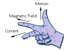
Direction of Induced current: Fleming’s right hand rule
According to Fleming’s right hand rule if we stretch 3 fingers of our right hand, then the :-
- Thumb will point to the motion of the conductor.
- First Finger points towards the magnetic field.
- Middle finger points to direction of the induced current.
Methods of producing Induced Emf in a circuit:Varying Magnetic Field (B)
- Consider a coil, a magnet and a galvanometer.
- As the magnet is brought near the coil,the magnetic field associated with the coil changes.
- Mathematically,
- Φ = BAcosθ if we change the strength of the magnetic field(B), the value of flux will change as a result emf is induced.
When the magnet is brought near the coil, magnetic field changes

When the magnet passes through the coil the is a deflection in the galvanometer

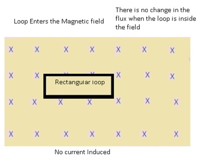
Methods of producing Induced Emf in a circuit: Varying Area(A)in a moving loop
If the area within the magnetic field changes, then emf will be induced.
- The rectangular loop enters the magnetic field and goes out of the field.
- Initially there is no magnetic field from where the loop is starting, the moment the loop enters the magnetic field it experiences the change in the magnetic field at the boundary.
- When the loop was inside the magnetic field there was no change in the magnetic flux.
- But when the loop leaves the region of magnetic field there was decrease in the magnetic flux.
- Because when it leaves the magnetic field area keeps on decreasing.
- As area decreases therefore flux also decreases.
- At both the boundaries there is change in the area,as a result there is change in the flux.
Therefore there will be induced current at the boundary.
Mathematically:-
- The emf which is induced is known as Motional emf because this emf is induced due to the motion of the conductors.
- Consider a conductor is moving out of the magnetic field with some velocity ‘v’.
- The part which is inside the field =’X’ and length of the conductor=’length’
- In time Δt, loop covers small distance Δx.
- Decrease in the area =-(length Δx),
- Where (-) ive sign shows decrease in area.
- Decrease in flux = dΦ =B.ΔA =-BlengthΔx where ΔA=change in area
- Therefore from Faraday’s Lenz’s law, Induced emf e= -(dΦ/dt)
- =d/dt(BlengthΔx)
- => Blength (Δx/Δt)
- Therefore Motional Emfe= Blengthv
- where (velocity) v= Δx/Δt
- Induced current =I=(e/R) =(Blengthv/R)
- where R=resistance of the loop
- Motional Emf comes into play when the area of the loop within the magnetic field changes.
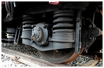
Brakes of the fast moving trains
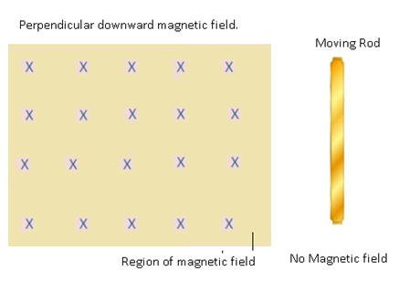
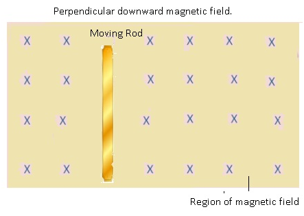
Methods of producing Induced Emf in a circuit: Varying Area (A) in a moving rod
- Consider a rod which is moving inside the magnetic field.
- When the loop enters the magnetic field; due to the magnetic fieldthe charges inside the rod experiences the magnetic force.
- Because of this magnetic force the (+) ive and (-) ive charges separate out from each other, i.e. all the (+)ive charges get accumulated at one end and (-)ive charges on the other end.
- Electrostatic potential is developed on the rod due to the accumulation of charges on both the ends of the rod when it enters the magnetic field.
- Because of electrostatic potential an emf is induced.
- This emf which was induced on the rod cannot be used for any practical purposes.
- As it is an open circuit therefore induced emf on the rod cannot be used.
- This induced emf is known as Motional Emf as it is generated because of motion of the rod inside the magnetic field.
- Expression for motional emfe= Blengthv
- Example: Flight.
- At the tips of both the wings of the aeroplane emf is induced.
- As it is not a closed loop so this emf cannot be used.

Problem:- An aircraft with a wingspan of 40m flies with a speed of 1080km/hr in the eastward direction at a constant altitude in the northern hemisphere, where the vertical component of earth’s magnetic field is 1.75×10⁻⁵T.Find the Emf that develops between the tips of the wings?
Answer:-
V=1080km/hr= ((1080×1000)/60) = 300m/s
B=1.75×10⁻⁵T
e=Blv=1.75×10-5 x40 x300
e=0.21V.
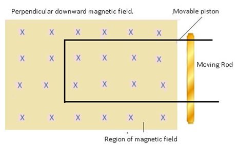
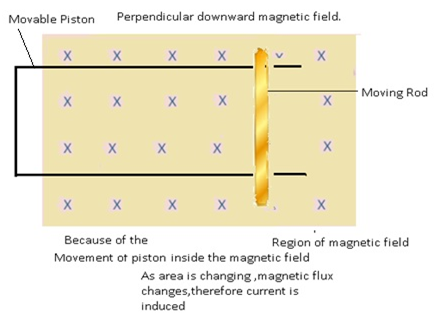
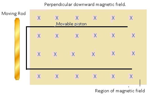
Methods of producing Induced Emf in a circuit: Varying Area (A) in a closed loop(with movable piston)
- Consider a closed loop such that one arm of the loop acts as a movable piston.
- The loop is present inside a magnetic field.
- The movement of piston will cause a change in area of the loop.
- As there is change in area as aresult there is change in flux because of which there is induced emf.
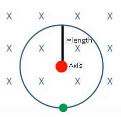
Problem:- A wheel with 10 metallic spokes each 0.5 m long is rotated with aspeed of 120 rev/min in a plane normal to the horizontal componentof earth’s magnetic field HE at a place. If HE = 0.4 G at the place, whatis the induced Emf between the axle and the rim of the wheel? Note that 1 G = 10–4 T.
Answer:-
Induced emf = (1/2) ω B R2
= (1/2) × 4π × 0.4 × 10–4 × (0.5)2
= 6.28 × 10⁻⁵ V
The number of spokes is immaterial because the emf across thespokes is in parallel.
Problem:-
A square loop of side 12 cm with its sides parallel to X and Y axes ismoved with a velocity of 8 cm s–1 in the positive x-direction in anenvironment containing a magnetic field in the positive z-direction.The field is neither uniform in space nor constant in time. It has a
gradient of 10 –3 T cm–1along the negative x-direction (that is it increasesby 10 – 3 T cm–1
as one moves in the negative x-direction), and it isdecreasing in time at the rate of
10 –3Ts–1. Determine the direction andmagnitude of the induced current in the loop if its resistance is 4.50 mΩ.
Answer:-
Side of the square loop, s = 12 cm = 0.12 m
Area of the square loop, A = 0.12 × 0.12 = 0.0144 m2
Velocity of the loop, v = 8 cm/s = 0.08 m/s
Gradient of the magnetic field along negative x-direction,
(dB/dx) =10-3Tcm-1 =10-1Tm-1
And, rate of decrease of the magnetic field,
(dB/dx) =10-3Ts-1
Resistance of the loop, R=4.5 mΩ=4.5×10⁻³Ω
Rate of change of the magnetic flux due to the motion of the loop in a non-uniform magnetic field is given as:
(dΦ/dt) =A x (dB/dt) xv
=144x 10-4xm2x10-1x0.08
=11.52×10⁻⁵Tm2s-1
Rate of change of the flux due to explicit time variation in field B is given as:
(dΦ/dt) =A x (dB/dt)
=144×10-5Tm2s-1
Since the rate of change of the flux is the induced Emf, the total induced Emf in the loop can be calculated as:
e=144×10-5+11.52×10-5
=12.96 x 10⁻⁵V
∴Induced current, i= (e/R) s
s= (12.96×10⁻⁵)/ (1.5×10⁻³)
i=2.88×10⁻²A
Hence, the direction of the induced current is such that there is an increase in the flux through the loop along positive z-direction.
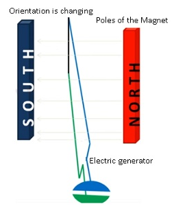
Methods of producing Induced Emf in a circuit: Varying angle between magnetic field and area vector (θ)
By changing the orientation of coil and magnetic field i.e. θ emf can be induced in the circuit.
Consider Φ = BA cosθ if θ is changed then the value of Φ will also change.
For Example:-
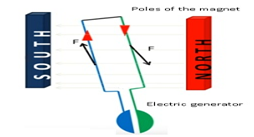
- Electric generator-In case of electric generator there are rectangular coils and they are placed between the poles of the electromagnet.
- When it is rotated then the orientation of the area vector of the coil and magnetic field is changing.
- As θ is changing from 0 to 900,900 to 1800, 1800 to 2700 and 2700 to 3600.
- As a result there is change in flux and as a result emf is induced in the generator which in turn induces current in the generator.
Problem:- A 1.0m long metallic rod is rotated with an angular frequency of 400rads-1 about an axis normal to the rod passing through its one end. The other end of the rod is contact with a metallic circular ring. A constant and uniform magnetic field of 0.5T parallel to the axis exists everywhere. Calculate the emf developed between the centre and the ring?
Answer:-
Length of the rod, l = 1 m
Angular frequency, ω = 400 rad/s
Magnetic field strength, B = 0.5 T
One end of the rod has zero linear velocity, while the other end has a linear velocity of l(i).
Average linear velocity of the rod, v=(l (i) +0)/2 = (l (i)/2)
Emf developed between the centre and the ring,
e=Blv =Bl (l (i)/2) = (Bl2(i)/2)
=(0.5x(1)2x400)/2
=100V.
Hence, the emf developed between the centre and the ring is 100 V.
Problem:- A rectangular wire loop of sides 8 cm and 2 cm with a small cut ismoving out of a region of uniform magnetic field of magnitude 0.3 Tdirected normal to the loop. What is the emf developed across thecut if the velocity of the loop is 1 cm s–1 in a direction normal to the longer side, (b) shorter side of the loop? For how long does the induced voltage last in each case?
Answer:-
Length of the rectangular wire, l = 8 cm = 0.08 m
Width of the rectangular wire, b = 2 cm = 0.02 m
Hence, area of the rectangular loop,A = lb
= 0.08 × 0.02
= 16 × 10 – 4
Magnetic field strength, B = 0.3 T
Velocity of the loop, v = 1 cm/s = 0.01 m/s
(a) Emf developed in the loop is given as:e = Blv
= 0.3×0.08×0.01 =2.4 x10⁻⁴V
Time taken to travel along the width = (Distance travelled)/ (velocity)
= (b/v) = (0.02/0.01) =2s
Hence, the induced voltage is 2.4 x10⁻⁴V which lasts for 2 s.
(b) Emf developed, e = Bbv
= 0.3×0.02×0.01=0.6×10⁻⁴V
Time taken to travel along the length, t=(Distance travelled)/(velocity)
=(1/v) =(0.08)/(0.01) =8s.
Hence, the induced voltage is 0.6 x10⁻⁴ V which lasts for 8 s.
Problem:- Suppose the loop in above problem is stationary but the current feeding the electromagnet that produces the magnetic field is gradually reduced so that the field decreases from its initial value of 0.3 T at the rate of 0.02 Ts–1. If the cut is joined and the loop has a resistance of 1.6 Ω, how much power is dissipated by the loop as heat? What is the source of this power?
Answer:-
Initial B = 0.3 T
(dB /dt) = 0.02Ts-1
ε =-(d Φ/dt) =-A (dB /dt)
Area, A = 8×10-2x2x10-2 =16×10-4m2
ε =16×10-4x0.02= 32×10-6V
i = (ε/R) = (32×10-6/1.6) =2×10⁻⁵ A
Power (ε i) = 6.4×10⁻¹⁰W
Source of this power is source that produces the changing magnetic field.
Eddy currents ( Electromagnetic Induction )
- Eddy currents are induced currents in the body of conductor when subjected to changing magnetic flux.
- They are also known as Foucault current after the name of the scientist Foucault.
- They are known as eddy currents as they are in the pattern of eddiesin the water.
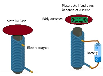
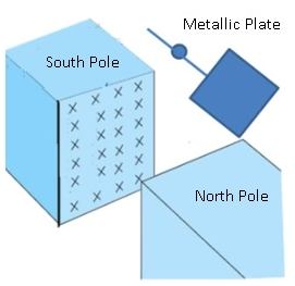
- Consider an electromagnet when attached to battery because of the current magnetic field will be produced which will induce current in the metallic plate.
- The current will be in the form of eddies.
- The metallic plate will be slightly drifted in the air because of eddy currents.
- Mathematically :-
- i=(induced emf)/(Resistance of the conductor)
- =(e/R)
- e= -(dΦ/dt)
- Therefore i=-(dΦ/dt)/R
- The magnitude and direction will be same as the induced current in the case of electromagnet induction.

Ripples in water
Examples of Eddy currents
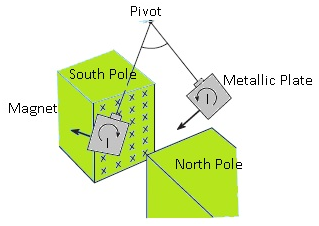
- Metal plate: In absence of magnetic field: No damping
- Consider a metal plate which is suspended freely with the help of thread.
- As there is no magnetic field the plate will keep on oscillating without damping.
- Metal plate: In presence of magnetic field: Damping exists
- If the magnetic field is present it oscillates but it stops after some time because of damping.
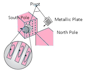
- As the plate keep on entering the magnetic plate and coming out of it.
- When it enters the region of magnetic field there is increase in area. As a result flux changes.
- As flux changes there is induced current.The direction of the induced current will be opposite to itsmean position.
- When the induced current leaves the magnetic field, again current will be induced but in the opposite direction.
- This effect of induced currents together gives the effect of eddy currents.
- Because of induced current the motion is dampedas they are opposing the motion of the plate.
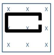
- Metal plate with slots: In presence of magnetic field: Damping reduced
- When the plate oscillates the damping is reduced as there is lesser area.
- The eddy currents are less as a result damping is reduced.
- Eddy currents willoppose the motion of the plate and as they are reduced so there the damping is reduced.
- Conclusion:-
- Eddy currents always have the tendency to oppose the relative motion.
- They are same eddies in the water because as the movement continues and currents also keep changing their direction depending on the change in flux.
- Therefore they look like eddies in the water.
- Eddy currents also cause damping as they oppose motion.
Eddy currents are generated in the copper plate,while entering and leaving the region of magnetic field.
Cutting slots in the copper plate reducesthe effect of eddy currents.
Eddy currents:Disadvantages
Dissipate electrical energy in the form of heat.
Overheating of metallic cores of transformers, electric motors and other such devices.
- In order to avoid the overheating of the core,metallic sheets are taken in the form of very thin sheets.These sheets are electrically insulated.
- The cores are insulated with some insulating material as a result heat won’t get transferred to surroundings.
- These cores are known as laminated cores.
By using these cores eddy currents are reduced as a result heat dissipation is reduced.
Eddy currents : Applications
Electromagnetic brakes –To control the speed of fast moving electric trains.
In case of fast moving trains,on the tracks, magnets are placed so that currents are induced on the wheels of the train.
Electromagnetic brakes do not need any maintenance. It is very economical alternative to friction brakes.
- Consider a very big magnet is placed near the track on which train will go.
- Outer rim of the wheel is coated with copper.
- When the wheel comes near the magnetic field it will experience the magnetic field produced by the magnet.
- This will result in change in flux and induced current will be produced.
- The direction will be given by Lenz’s law.The induced field will give rise to repulsiveinduced field at the boundary.As a result the train slows down a little.
- When the train moves to other end of the magnet it will experience an attractive force because of induced current in the opposite direction.
- Train gradually slows down and finally comes to rest.
- The kinetic energy lost by the train = the heat gained by the copper.
- It obeys the law of conservation of energy.

Electromagnetic damping:- Electromagnetic damping in galvanometers helps to reduce oscillations around equilibrium positions.
- Galvanometers are the instruments which help in measuring currents.
- When the current passes through the galvanometer there is a needle(needle is like a small metal plate) which oscillate after some time it comes to rest.
- Because of electromagnetic dampingneedle comes to rest quickly.As a result magnitude of current can be detected.
- It is same as metal plate entering the magnetic field there is a current induced similarly when leaving the magnetic field there is a current induced.
- The current entering and leaving are in opposite directions.
- These eddy currents oppose the relative motion as a result electromagnetic damping occurs.
Induction ( Electromagnetic Induction )
Induction is defined as current production in the coil due to the change in magnetic flux in itself or another coil.
Types of Induction:-
- Self-induction-
- There will be change in the magnetic flux in the coil itself because of which a current will be induced in itself.
- It is denoted by L.

- Mutual induction-
- There are 2 coils,if there is change in the magnetic flux in one coil then the magnetic field is induced in the second coil.
- It is denoted by M.

Inductance:-
- Inductance is a quantity which measures the induction.
- It is also called as Coefficient of induction.
- Coefficient of inductionis about the ratio of current induced with respect to magnetic flux.
- Flux through the coil Φ∝ I (current)
- If there are N turns in the coil,
- Total Flux is known as flux linkage NΦ∝ I=> NΦ =constant I
- This constant of proportionality is known as Inductance.
- It is a scalar quantity.
- I. unit is Henry(H).
- It depends on
- Geometry of the coil.
- Nature of the material on which it is wound.
Self-Inductance
- There is one coil in which there is change in the flux in that coil and because of that flux change.
- Current is induced in the same coil.
- Current tries to oppose the change in the flux.
- Consider a closed circuit,as a result the current will flow through the coil,therefore flux increases as a result current is induced in the coil.
- This induced current will oppose the growth of current.
- Suppose there is N number of turns in the coil.Therefore flux linkage of the coil N Φ∝ I.
- N Φ =LI where L=constant of proportionality and is known as self-inductance.
- Therefore Self-inductance will describe about the ratio of magnetic flux to the current it induces.
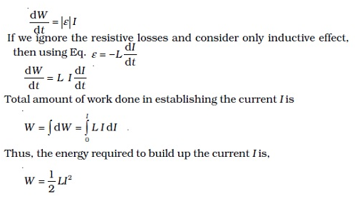
- Induced Emf e=-(d Φ/dt) By faraday’s Lenz’s law
- Therefore e=-d/dt [LI]
- e= -L dI/dt Where I=current flows through the coil.
- This Emf will oppose the change in I.
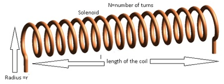
Self-inductance of a long solenoid
- Long solenoid is the one whose length(length) is very large as compared to radius(r) of the solenoid.(l>>r)
- Using B=μ0nI
- =(μ0NI)/length where N= total number of turns, n= number of turns per unit length.
- Case 1:- core of the solenoid has air.
- Flux=NBA
- =NA((μ0NI)/length).
- =>Φ =(μ0N2IA)/length (equation(1))
- Also total flux=LI (equation(2))
- From (1) and (2)
- => LI =(μ0N2IA)/length
- =>L = (μ0N2A)/length
- Case 2:- core of the solenoid is made of material which has permeability μr.
- L=(μr N2A)/length
- =>L= (μ0 μr N2 A)/length
Problem:- A long solenoid with 15 turns per cm has a small loop of area 2.0 placed inside the solenoid normal to its axis. If the current carried by the solenoid changes steadily from 2.0 A to 4.0A in 0.1 s, what is the induced emf in the loop while the current is changing?
Answer: – Number of turns on the solenoid = 15 turns/cm = 1500 turns/m
Number of turns per unit length, n = 1500 turns
The solenoid has a small loop of area, A =2.0 cm2= 2 × 10⁻⁴m2
Current carried by the solenoid changes from 2 A to 4 A.
Therefore change in current in the solenoid, di = 4 – 2 = 2 A
Change in time, dt = 0.1 s
Induced emf in the solenoid is given by Faraday’s law as:
e= (dΦ/dt) … (i)
Where, Φ= Induced flux through the small loop
= BA … (ii) Where B = Magnetic field
= (μ0ni) … (iii)
μ0 = Permeability of free space
=4nx10-7H/m
Hence, equation (i) reduces to:
e= (d/dt) (di/dt)
=Aμ0n x (di/dt)
=2×10-4x4x3.14×10-7x 1500 x (2/0.1)
=7.54 x 10⁻⁶V
Hence, the induced voltage in the loop is 7.54×10⁻⁶V
Back Emf
- Self-induced Emf is also known as back Emf.
- Back Emf tries to oppose change in the current.It tries to bring back the current.
- This implies the current needs to do work against back Emf.
- The work done by the current is stored as magnetic potential energy.
- In a coil there is increase in the current as a result there is change in the magnetic flux because of that there is induced Emf.
- This induced Emftry to oppose the change in the current.
- The current will do some work to oppose the back Emf.
- This work done is stored as magnetic potential energy.
- Mathematically:-
- Work done = Potential Energy
- Note: – Self-inductance acts like inertia.
Problem:- An air-cored solenoid with length 30 cm, area of cross-section 25 cm2 and number of turns 500, carries a current of 2.5 A. The current is suddenly switched off in a brief time of 10–3 s. How much is the average back emf induced across the ends of the open switch in the circuit? Ignore the variation in magnetic field near the ends of the solenoid.
Answer:- Length of the solenoid, l = 30 cm = 0.3 m
Area of cross-section, A = 25cm2 =25×10-4m2
Number of turns on the solenoid, N = 500
Current in the solenoid, I = 2.5 A
Current flows for time, t = 10-3 s
Average back emf, e= (dΦ/dt) … (i)
Where,dΦ = Change in flux
= NAB … (2)
Where,
B = Magnetic field strength
= μ0 (NI/length)
Where,
μ0= Permeability of free space =4nx10s-7xTmA-1
Using equations (2) and (3) in equation (1), we get
e= (μ0N2IA)/ (t length)
= (4×3.14×10-7x (500)2x2.5x25x10-4)/ (3.0×10⁻³)
=6.5V
Hence, the average back emf induced in the solenoid is 6.5 V.
Mutual Inductance
In mutual inductance there are 2 coils, current is passed in one coil, as current increases there is change in the flux, and as aresult current is induced in the second coil.
Consider coil 1 connected to battery and coil 2 is connected to the galvanometer.
- When the key is pressed attached to the coil 1 the current starts flowing, when the current starts increasing flux linked also starts increasing.
- Because of the increase in the flux linked with the coil1, the flux of coil 2 also increases.
- There is change in the flux of the coil 2 as a result emf is induced in the coil 2.
- Because of the induced emf induced current will be there in coil2.
- This induced current opposes the increase of the current in coil 1.
Mathematically:-
- Φ(2)∝ I(1)
- =>Φ(2) = MI(1)where M = constant of proportionality known as Mutual Inductance.
- Induced emf in coil 2 e=-(dΦ(2)/dt)
- =>e =-d/dt(MI (1)) where I current flowing in coil (1).
- Therefore e =-d/dt (M I (1))
- M (mutual inductance) depends on:-
- Geometry of both coils.
- Distance between coils.
- Orientation of coils.
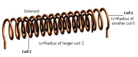
Mutual Inductance between long co-axial solenoids
- Co-axial solenoids means the centres of both the solenoids are same.
- Radius of the smaller solenoid (1) =r1. Number of turns in smaller solenoid= N1.
- Radius of the bigger solenoid (2) = r2.Number of turns in bigger solenoid= N2.
Case 1:-
- Current flowing in the bigger solenoid = I2, as a result magnetic flux Φ1 will be induced in smaller solenoid.
- Therefore N1Φ1∝I2
- =>N1Φ1 =M12I2 equation(1)
- where M12 = mutual inductance of 1 w.r.t 2
- Magnetic field due to I2 in (bigger solenoid 2) B =μ0n2I2
- => B =(μ0n2I2)/length
- Total Flux N1Φ1 =N1 BA1
- => =(N1A1μ0N2I2)/length equation(2)
- From equation(1) and (2)
- M12I2 = (N1A1μ0N2I2)/length
- =>M12 = (μ0N1 N2A)/ length equation(a)
Case 2:-
- Current I1 flowing through solenoid (1) this will result in flux solenoid (2)
- Total flux N2Φ2 = M21I1 equation(3)
- Also total flux N2Φ2 = N2 B1 A1
- where B =magnetic field due to smaller solenoid;
- B1 =μ0n1I1;
- =(μ0N1I1)/length
- =>N2Φ2 = N2((μ0N1I1)/length)A1 equation(4)
- Comparing (3) and (4)
- M21I1 = N2((μ0N1I1)/length)A1
- M21 = (μ0N2 N1A1)/ length equation(b)
- Comparing (a) and (b)
- ThereforeM12 = M21
Problem:- A solenoid of length 50cm with 20 turns per cm and area of cross-section 40cm2 completely surrounds another co-axial solenoid of the same length, area of cross section 25cm2 with 25 turns per cm. Calculate the mutual inductance of the system?
Answer:- Let the outer solenoid be 1 and inner solenoid be 2.
Length l1 =50cm=50×10-2m
n1 =2000 turns /m
A1 = 40 x10-4 m2
Length l2=50×10-2m
n2 =2500 turns/m
A2=25×10-4 m2
M12=M21
M12= (μ0N1N2A2)/length =μ0n1n2A2length
=4×3.14×10-7x2000x2500x50x10-2x25x10-4
=7.85×10⁻³ H
Problem:- (a) A toroidal solenoid with an air core has an average radius of 15cm, area of cross-section 2cm2 and 1200 turns. Obtain the self-inductance of the toroid. Ignore field variations across the cross-section of toroid.
(b) A second coil of 300 turns is wound closely on the toroid above. If the current in the primary coil is increased from 0 to 2A in 0.05s.Obtain the induced emf in the second coil.
Answer:- (a) Radius r1=15×10-2m
Area A1=2×10⁻⁴m2
N1=1200
B=μ0nI= (μ0N1I)/ (2πr1)
Total flux: -N1xBxA1=N1x(μ0xN1I/2πr1) x A1
Also Total flux =LI
LI =μ0xA1x N12I/ (2πr1)
= (4πx10-7x (1200)2x 2×10-4)/ (2πx15x10-2)
=2.304×10⁻⁴ H
The self-inductance of the toroid is 2.304×10⁻⁴ H.
(b) A1=2×10⁻⁴m2
r1=15×10-2m
N1=1200
N2 =300
(dI1/ dt) = (If –Ii)/dt = (2-0)/ (0.05) =40A/s
Total flux in 2:- Φ2 =N2xB1xA1
=N2(μ0n1I1)/A1 equation (1)
Also,Φ2 =MI1 equation (2)
=> M=N2xμ0xn1xA1
e2 =M (dI1/dt) =μ0N2n1A1x40
=4πx10-7x 300x (N1/2πr1) x2x10-4x40
=0.023V
The emf induced in the second coil is 0.023V.
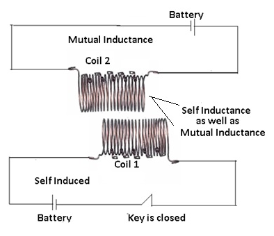
Self and Mutual Inductance
- Consider a coil (1) which is connected to a battery and there is a key.
- There is another coil (2) which is connected to galvanometer.
- When the key is closed, the current flows through coil (1) there is a change in the flux of coil (1) because of which self-induced emf will be produced.
- Because of current flow in coil(1) there will be change in the magnetic flux of coil(2) because of which induced emf will be produced in coil(2).
- As a result mutual induction takes place in coil(2).
- This shows both self-inductance and mutual inductance takes place simultaneously.
- Therefore flux linked to coil 1:-N1Φ1 =L1I1 +M12I2
- Induced emf in coil (1) e= -L1(dI1/dt) – M12(dI2/dt)
- Where(-)ive sign shows it opposes the growth of current.
Problem:- Two coils have mutual inductance of 1.5 H. If the current in the primary circuit is raised to 5A in 1 millisecond after closing the circuit, what is the emf induced in the secondary?
Answer:-
M=1.5 H
Ii=0 A, If=5A, dt =1ms =10-3sec
e2 =-M (dIi/dt)
=1.5 x ((If-Ii)/dt)
=1.5 x ((5-0)/10-3)
=7.5x10³V.
Problem:- Two concentric circular coils, one of small radius r1 and the other of large radius r2, such that r1<< r2, are placed co-axially with centres coinciding. Obtain the mutual inductance of the arrangement.
Answer:-
Let a current I2 flow through the outer circular coil. The field at the centre of the coil is
B2 = μ0I2 / 2r2. Since the other co-axially placed coil has a very small radius, B2 may be considered constant over its cross-sectional area. Hence,
Φ1 = πr12 B2
=I2 (μ0 π r12)/ (2r2)
= M12I2
Thus, M12 = (μ0 π r12)/ (2r2)
Using equation M12=M21= (μ0 π r12)/ (2r2)
Note that we calculated M12 from an approximate value of Φ1, assuming the magnetic field B2 to be uniform over the area π r12. However, we can accept this value because r1 << r2.
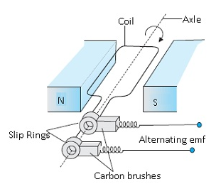
AC Generator
- An electrical generator is a device that converts mechanical energy to electrical energy.
- The generation of alternating currents (ac) is based on the phenomenon of electromagnetic induction.
- Whenever the magnetic flux changes an emf will be induced in the coil.
- AC generator is a device that converts mechanical energy into electrical energy(alternating currents).
- AC generator is an example of inducing an emf or current in a loop by varying the magnetic field and area vector.
Principle:-
- Current is induced in a loop through a change in its orientation or a change in its effective area.
- Induced emf is produced either by changing θ or by changing the area vector.
- Direction of current is given by Fleming’s right hand rule.
- Direction of the current in the circuit changes by the up and down movement of the loops.
Construction:-
- It consists of 2 poles(north and south) of a magnet in order to have uniform magnetic field.
- There is a coil of rectangular shape also known as armature.
- The armature is connected to 2 slip rings.
- Slip rings helps in electrical contact with the brushes.It does not change current direction.
- The slip rings provide a continuous connectionwith the wire around the armature.
- These slip rings are attached to carbon brushes.
- The rectangular coil is capable of rotating about an axis which is perpendicular to the magnetic field.
- The axis of rotation is known as axle.
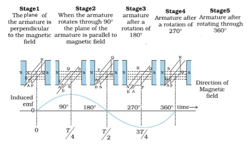
Working:-
- At initial time t=0;θ =0 where θ = angle between magnetic field (B) and area vector.
- Magnetic flux Φ =BA as cos 0 =1.
- When the coil rotates with the angular velocity ω;
- After time t, θ = ωt;
- Φ(t) =BA cosθ = BA cosωt (because θ is changing as a result magnetic flux is also changing)
- Therefore change in flux occurs; By Faraday’s Law there will be induced emf.
- Induced emf e=- N (dΦ/dt); where N = number of turns.
- = –Nd(BA cosωt)/dt
- e=NBAωsinωt
- As sinωt is a periodic function,therefore it varies from -1 to +1.
- Minimum value of e= – NBAω and maximum value of e=+ NBAω.
- Therefore e =e0sinωt where e0=NBAω
- Therefore Induced current will change periodically.
- As the current is changing periodically that is why it is called as alternating current.
- Rod is getting rotated by some external means; therefore rotation of rod is mechanical energy.
- This mechanical energy is getting converted toinduce emf because of which induced current is produced.
- Therefore because of mechanical energy alternating current is generated.As a result electrical energy is generated.


Types of Generator:-
- Hydro-electric generators:Power of flowing water is used to rotate the rectangular coil.
- Thermal generators: – When thermal power is used to rotate the rectangular coil.
- Power generators
Download the pdf file for chapter 6 Electromagnetic Induction
Chapter-6-Electro-Magnetic-InductionMost Important Question of Electromagnetic Induction
1 Mark Questions ( Electromagnetic Induction )
1. A metallic wire coil is stationary in a non – uniform magnetic field. What is the emf. Induced in the coil?
Ans. NO emf is induced in the coil as there is no change in the magnetic flux linked with the secondary coil.
2. Why does metallic piece becomes very hot when it is surrounded by a coil carrying high frequency (H.F) alternating current?
Ans. When a metallic piece is surrounded by a coil carrying high frequency (H.F) alternating current, it becomes hot because eddy currents are produced which in turn produces joule’s heating effect.
3. An electrical element X when connected to an alternating voltage source has current through it leading the voltage by radian. Identify X and write expression for its reactance?
Ans. X is a purely capacitive circuit
4. A transformer steps up 220 V to2200 V. What is the transformation ratio?
Ans.
5. The induced emf is also called back emf. Why?
Ans. it is because induced emf produced in a circuit always opposes the cause which produces it.
6. Why the oscillations of a copper disc in a magnetic field are lightly damped?
Ans. Copper disc oscillates because of the production of eddy currents which opposes its oscillating motion and as a result the motion gets damped.
7.A metallic wire coil is stationary in a non – uniform magnetic field. What is the emf. Induced in the coil?
Ans.NO emf is induced in the coil as there is no change in the magnetic flux linked with the secondary coil.
2 Marks Questions ( Electromagnetic Induction )
1. IF the rate of change of current of 2A/s induces an emf of 1OmV in a solenoid. What is the self-inductance of the solenoid?
Ans.
2. A circular copper disc. 10 cm in radius rotates at a speed of 2 rad/s about an axis through its centre and perpendicular to the disc. A uniform magnetic field of 0.2T acts perpendicular to the disc.
1) Calculate the potential difference developed between the axis of the disc and the rim.
2) What is the induced current if the resistant of the disc is 2?
Ans. (1) Radius = 10cm, B = 0.2T w = 2 rad/s
I = 0.0314 A
3. An ideal inductor consumes no electric power in a.c. circuit. Explain?
Ans. P = E rms I rms cos
But for an ideal inductor
P=0
4. Capacitor blocks d.c. why?
Ans. The capacitive reactance
For d.c. = 0
Since capacitor offers infinite resistance to the flow of d.c. so d.c. cannot pass through the capacitor.
5. Why is the emf zero, when maximum number of magnetic lines of force pass through the coil?
Ans. The magnetic flux will be maximum in the vertical position of the coil. But as the coil rotates
Hence produced emf
6. An inductor L of reactance is connected in series with a bulb B to an a.c. source as shown in the figure.
Briefly explain how does the brightness of the bulb change when
(a) Number of turns of the inductor is reduced.
(b) A capacitor of reactance is included in series in the same circuit.
Ans. (a) Since Z =
When number of turns of the inductor gets reduced and Z decreases and in turn current increases
Hence the bulb will grow more brightly
(b) When capacitor is included in the circuit
But (given)
Z = R (minimum)
Hence brightness of the bulb will become maximum.
7. A jet plane is travelling towards west at a speed of 1800 km/h. What is the voltage difference developed between the ends of the wing having a span of 25 m, if the Earth’s magnetic field at the location has a magnitude of and the dip angle is
Ans. Speed of the jet plane, v = 1800 km/h = 500 m/s
Wing span of jet plane, l = 25 m
Earth’s magnetic field strength, B =
Angle of dip, s
Vertical component of Earth’s magnetic field,
BV = B sin
=
=
Voltage difference between the ends of the wing can be calculated as:
=
= 3.125 V
Hence, the voltage difference developed between the ends of the wings is
3.125 V.
8. A pair of adjacent coils has a mutual inductance of 1.5 H. If the current in one coil changes from 0 to 20 A in 0.5 s, what is the change of flux linkage with the other coil?
Ans. Mutual inductance of a pair of coils, µ = 1.5 H
Initial current, = 0 A
Final current = 20 A
Change in current,
Time taken for the change, t = 0.5 s
Induced emf,
Where is the change in the flux linkages with the coil.
Emf is related with mutual inductance as:
Equating equations (1) and (2), we get
Hence, the change in the flux linkage is 30 Wb.
9. A horizontal straight wire 10 m long extending from east to west is falling with a speed of , at right angles to the horizontal component of the earth’s magnetic field, Wb .
(a) What is the instantaneous value of the emf induced in the wire?
(b) What is the direction of the emf?
(c) Which end of the wire is at the higher electrical potential?
Ans. Length of the wire, l = 10 m
Falling speed of the wire, v = 5.0 m/s
Magnetic field strength, B =
(a) Emf induced in the wire,
e = Blv
(b) Using Fleming’s right hand rule, its can be inferred that the direction of the induced emf is from West to East.
(c) The eastern end of the wire is at a higher potential.
10. A 1.0 m long metallic rod is rotated with an angular frequency of 400 rad about an axis normal to the rod passing through its one end. The other end of the rod is in contact with a circular metallic ring. A constant and uniform magnetic field of 0.5 T parallel to the axis exists everywhere. Calculate the emf developed between the centre and the ring.
Ans. Length of the rod, l = 1 m
Angular frequency, = 400 rad/s
Magnetic field strength, B = 0.5 T
One end of the rod has zero linear velocity, while the other end has a linear velocity of.
Average linear velocity of the rod,
Emf developed between the centre and the ring,
Hence, the emf developed between the centre and the ring is 100 V.
11. Use Lenz’s law to determine the direction of induced current in the situations described by Fig. 6.19:
(a) A wire of irregular shape turning into a circular shape;
(b) A circular loop being deformed into a narrow straight wire.
Ans. According to Lenz’s law, the direction of the induced emf is such that it tends to produce a current that opposes the change in the magnetic flux that produced it.
(a) When the shape of the wire changes, the flux piercing through the unit surface area increases. As a result, the induced current produces an opposing flux. Hence, the induced current flows along adcb.
(b) When the shape of a circular loop is deformed into a narrow straight wire, the flux piercing the surface decreases. Hence, the induced current flows along
3 Marks Questions ( Electromagnetic Induction )
1. How is the mutual inductance of a pair of coils affected when
(1) Separation between the coils is increased.
(2) The number of turns of each coil is increased.
(3) A thin iron sheet is placed between two coils, other factors remaining the same. Explain answer in each case.
Ans. (1) When the Separation between the coils is increased, the flux linked with the
secondary coils decreases, hence mutual induction decreases.
(2) Since m =so when increases, mutual induction increase.
(3) Mutual induction will increase because
(Relative permeability of material)
2. Distinguish between resistances, reactance and impedance of an a.c. circuit?
Ans.
| Resistance | Reactance | Impedance | |
| 1 | Opposition offered by the resistor to the flow of current | Opposition offered by the inductor or capacitor to the flow of current | Opposition offered by the combination of resistor, inductor or capacitor |
| 2 | It is independent of the frequency of the source. | It depends on the frequency of the source | It depends on the frequency of the source |
3. A sinusoidal voltage V = 200 sin 314t is applied to a resistor of 10 resistance. Calculate
(1) rms value of the voltage
(2) rms value of the current
(3) Power dissipated as heat in watt.
Ans. V = 200 sin 314t
V = Vo sin wt
Vo = 200V, w = 314 rad/s.
R = 10
(1) V rms =
V rms = 200 = 282.8 V
(2)
I rms = 28.28 A
(3) Since circuit is purely resistive
P = 7.998 watt
4. Obtain an expression for the self inductance of a long solenoid? Hence define one Henry?
Ans. Consider a long solenoid of area A through which current I is flowing
Let N be the total number of turns in the solenoid
Total flux = NBA
Here = B =
Where n is no. of turns per unit length of the solenoid
N = nl
Equation (1) & (2)
[n = N/]
One Henry – if current is changing at a rate of 1 A/s in a coil induces an emf. of 1 volt in it then the inductance of the coil is one henry.
5. A conducting rod rotates with angular speed w with one end at the centre and other end at circumference of a circular metallic ring of radius R, about an axis passing through the centre of the coil perpendicular to the plane of the coil A constant magnetic field B parallel to the axis is present everywhere. Show that the emf. between the centre and the metallic ring is
Ans. Consider a circular loop connect the centre with point P with a resistor.
The potential difference across the resistor = induced emf.
Rate of change of area of loop.
If the resistor QP is rotated with angular velocity w and turns by an angle in time t then
Area swept
6. (a) At a very high frequency of a.c., capacitor behaves as a conductor. Why?
(b) Draw the graph showing the variation of reactance of
(i) A capacitor
(ii) An inductor with a frequency of an a.c. circuit.
Ans. (a)
For a.c. when
Thus at a very high frequency of a.c. capacitor behaves as a conductor
(b)
7. Calculate the current drawn by the primary of a transformer which steps down 200 V to 20 V to operate a device of resistance 20. Assume the efficiency of the transformer to be 80%?
Ans.= 80% Ep = 200V Es = 20V Z = 20
Ip = 0.125 A
8. An a.c. voltage E = Eo sin wt is applied across an inductance L. obtain the expression for current I?
Ans.E = Eo sin wt (Given)
Emf produced across L =
Total emf of the circuit =
Since there is no circuit element across which potential drop may occur
Integrating
(peak vlue of current)
I = Io sin
9. A series circuit with L = 0.12H, C = 0.48mF and R = 25is connected to a 220V variable frequency supply. At what frequency is the circuit current maximum?
Ans.L = 0.12H, C = 0.48mF =
R = 25 Ev = 220V
In the circuit when I is maximum, R will be minimum
f = 21 Hz
10. A rectangular wire loop of sides 8 cm and 2 cm with a small cut is moving out of a region of uniform magnetic field of magnitude 0.3 T directed normal to the loop. What is the emf developed across the cut if the velocity of the loop is in a direction normal to the (a) longer side, (b) shorter side of the loop? For how long does the induced voltage last in each case?
Ans. Length of the rectangular wire, l = 8 cm = 0.08 m
Width of the rectangular wire, b = 2 cm = 0.02 m
Hence, area of the rectangular loop,
A = lb
Magnetic field strength, B = 0.3 T
Velocity of the loop, v = 1 cm/s = 0.01 m/s
(a) Emf developed in the loop is given as:
e = Blv
=
Time taken to travel along the width. ts
Hence, the induced voltage is which lasts for 2 s.
(b) Emf developed, e = Bbv
=
Time taken to travel along the length,
t
Hence, the induced voltage is which lasts for 8 s.
11. Current in a circuit falls from 5.0 A to 0.0 A in 0.1 s. If an average emf of 200 V induced, give an estimate of the self-inductance of the circuit.
Ans. Initial current,
Final current,
Change in current,
Time taken for the change, t = 0.1
Average emf, e = 200 V
For self-inductance (L) of the coil, we have the relation for average emf as:
e = L s
s
Hence, the self-induction of the coil is 4 H.
12. Suppose the loop in Exercise 6.4 is stationary but the current feeding the electromagnet that produces the magnetic field is gradually reduced so that the field decreases from its initial value of 0.3 T at the rate of . If the cut is joined and the loop has a resistance of 1.6 how much power is dissipated by the loop as heat? What is the source of this power?
Ans. Sides of the rectangular loop are 8 cm and 2 cm.
Hence, area of the rectangular wire loop,
Initial value of the magnetic field,
Rate of decrease of the magnetic field,
Emf developed in the loop is given as:
Where,
= Change in flux through the loop area
= AB
Resistance of the loop, R = 1.6
The current induced in the loop is given as:
Power dissipated in the loop in the form of heat is given as:
The source of this heat loss is an external agent, which is responsible for changing the magnetic field with time.
13. An air-cored solenoid with length 30 cm, area of cross-section and number of turns 500, carries a current of 2.5 A. The current is suddenly switched off in a brief time of . How much is the average back emf induced across the ends of the open switch in the circuit? Ignore the variation in magnetic field near the ends of the solenoid.
Ans. Length of the solenoid, l = 30 cm = 0.3 m
Area of cross-section, A =
Number of turns on the solenoid, N = 500
Current in the solenoid, I = 2.5 A
Current flows for time, t = s
Average back emf,
Where,
= Change in flux
= NAB ……(2)
Where,
B = Magnetic field strength
Where,
= Permeability of free space =
Using equations (2) and (3) in equation (1), we get
Hence, the average back emf induced in the solenoid is 6.5 V.
14. A line charge per unit length is lodged uniformly onto the rim of a wheel of mass M and radius R. The wheel has light non-conducting spokes and is free to rotate without friction about its axis (Fig. 6.22). A uniform magnetic field extends over a circular region within the rim. It is given by,
= 0 (otherwise) What is the angular velocity of the wheel after the field is suddenly switched off?
Ans. Line charge per unit length
Where,
r = Distance of the point within the wheel
Mass of the wheel = M
Radius of the wheel = R
Magnetic field,
At distance r, the magnetic force is balanced by the centripetal force i.e.,
Where
V=linear velocity of the wheel
∴ Angular velocity,
5 Marks Questions ( Electromagnetic Induction )
1. (a) State the condition under which the phenomenon of resonance occurs in a series LCR circuit. Plot a graph showing the variation of current with frequency of a.c. sources in a series LCR circuit.
(b) Show that in a series LCR circuit connected to an a.c. source exhibits resonance at its natural frequency equal to
Ans. (a) In a series LCR circuit
Resonance occurs when
The variation of current with frequency of a.c. source in series LCR circuit
(b) Electrical resonance takes place in a series LCR circuit when circuit allows maximum alternating current for which
Impedance Z =
For electrical resonance
Where w is the natural frequency of the circuit.
2. In a step up transformer, transformation ratio is 100. The primary voltage is 200 V and input is 1000 watt. The number of turns in primary is 100. Calculate
(1) Number of turns in the secondary
(2) Current in the primary
(3) The voltage across the secondary
(4) Current in the secondary
(5) Write the formula for transformation ratio?
Ans. (1) k = 100, Ep = 200V
EpIp = 1000 W, Np = 100
NS = 10,000
(2) EpIp = 1000W
Ip = 5A
(3)
Es = 20000 Volt
(4)
Is = 0.05 A
(5) For step up Trans former k > 1
3. Drive an expression for the average power consumed in a.c. series LCR circuit. Hence define power factor?
Ans. For an a.c. series circuit
E = Eo sin wt
And I = Io sin (wt +)
Where is the phase angle by which current leads the emf.
Now using dw = EIdt
dw = (Eo sin wt) (Io sin (wt +) )dt
dw = EoIo sin wt (sin wt cos + cos wt sin)dt
dw = EoIo (wt cos + sin wt cos wt sin)dt
Integrating within limits t = o to t = T
Hence average power consumed in a.c circuit is given by
Pav = EvIv cos —–(1)
Power factor – In the above expression
Cos is termed as power factor
When cos = 1 =
It means circuit is purely resistive and Pav = EvIv
When cos = 0 =
It means circuit is purely capacitive or inductive.
Pav = 0
Hence
4. Predict the direction of induced current in the situations described by the following Figs. 6.18(a) to (f ).
(a)
(b)
(c)
(d)
(e)
(f)
Ans. The direction of the induced current in a closed loop is given by Lenz’s law. The given pairs of figures show the direction of the induced current when the North pole of a bar magnet is moved towards and away from a closed loop respectively. Using Lenz’s rule, the direction of the induced current in the given situations can be predicted as follows:
(a) The direction of the induced current is along qrpq.
(b) The direction of the induced current is along prqp.
(c) The direction of the induced current is along yzxy.
(d) The direction of the induced current is along zyxz.
(e) The direction of the induced current is along xryx.
(f) No current is induced since the field lines are lying in the plane of the closed loop.
5. A long solenoid with 15 turns per cm has a small loop of area 2.0 placed inside the solenoid normal to its axis. If the current carried by the solenoid changes steadily from 2.0 A to 4.0 A in 0.1 s, what is the induced emf in the loop while the current is changing?
Ans. Number of turns on the solenoid = 15 turns/cm = 1500 turns/m
Number of turns per unit length, n = 1500 turns
The solenoid has a small loop of area, A =
Current carried by the solenoid changes from 2 A to 4 A.
Change in current in the solenoid, di = 4 – 2 = 2 A
Change in time, dt = 0.1 s
Induced emf in the solenoid is given by Faraday’s law as:
……(i)
Where,
= Induced flux through the small loop
= BA …(ii)
B = Magnetic field
=
= Permeability of free space
Hence, equation (i) reduces to:
Hence, the induced voltage in the loop is
6. A circular coil of radius 8.0 cm and 20 turns is rotated about its vertical diameter with an angular speed of 50 in a uniform horizontal magnetic field of magnitude . Obtain the maximum and average emf induced in the coil. If the coil forms a closed loop of resistance , calculate the maximum value of current in the coil. Calculate the average power loss due to Joule heating. Where does this power come from?
Ans. Max induced emf = 0.603 V
Average induced emf = 0 V
Max current in the coil = 0.0603 A
Average power loss = 0.018 W
(Power comes from the external rotor)
Radius of the circular coil, r = 8 cm = 0.08 m
Area of the coil,
Number of turns on the coil, N = 20
Angular speed, = 50 rad/s
Magnetic field strength, B =
Resistance of the loop, R = 10
Maximum induced emf is given as:
= 0.603 V
The maximum emf induced in the coil is 0.603 V.
Over a full cycle, the average emf induced in the coil is zero.
Maximum current is given as:
Average power loss due to joule heating:
The current induced in the coil produces a torque opposing the rotation of the coil. The rotor is an external agent. It must supply a torque to counter this torque in order to keep the coil rotating uniformly. Hence, dissipated power comes from the external rotor.
7. A square loop of side 12 cm with its sides parallel to X and Y axes is moved with a velocity of in the positive x-direction in an environment containing a magnetic field in the positive z-direction. The field is neither uniform in space nor constant in time. It has a gradient of along the negative x-direction (that is it increases by as one moves in the negative x-direction), and it is decreasing in time at the rate of . Determine the direction and magnitude of the induced current in the loop if its resistance is 4.50 .
Ans. Side of the square loop, s = 12 cm = 0.12 m
Area of the square loop,
Velocity of the loop, v = 8 cm/s = 0.08 m/s
Gradient of the magnetic field along negative x-direction,
And, rate of decrease of the magnetic field,
Resistance of the loop,
Rate of change of the magnetic flux due to the motion of the loop in a non-uniform magnetic field is given as:
Rate of change of the flux due to explicit time variation in field B is given as:
Since the rate of change of the flux is the induced emf, the total induced emf in the loop can be calculated as:
∴Induced current, s
s
Hence, the direction of the induced current is such that there is an increase in the flux through the loop along positive z-direction.
8. It is desired to measure the magnitude of field between the poles of a powerful loud speaker magnet. A small flat search coil of area with 25 closely wound turns, is positioned normal to the field direction, and then quickly snatched out of the field region. Equivalently, one can give it a quick turn to bring its plane parallel to the field direction). The total charge flown in the coil (measured by a ballistic galvanometer connected to coil) is 7.5 mC. The combined resistance of the coil and the galvanometer is 0.50 . Estimate the field strength of magnet.
Ans. Area of the small flat search coil, A =
Number of turns on the coil, N = 25
Total charge flowing in the coil, Q = 7.5 mC =
Total resistance of the coil and galvanometer, R = 0.50
Induced current in the coil,
Induced emf is given as:
Where,
= Charge in flux
Combining equations (1) and (2), we get
Initial flux through the coil, = BA
Where,
B = Magnetic field strength
Final flux through the coil,
Integrating equation (3) on both sides, we have
But total charge,
Hence, the field strength of the magnet is 0.75 T.
Download the class 12th Physics notes and important question chapter wise (Click Here)
Mohd. Sharif Qualification: B.Tech (Mechanical Engineering) [Founder of Wisdom Academy] [Aim Foundation & Free-Education.In] [Engineer By Profession | Teacher By Choice] [Blogger, YouTube Creator]