Field and Field Lines
Magnet
A magnet is a material that produces a field that attracts or repels other such materials of magnetic nature.
Lodestone is a naturally occurring magnet. It attracts materials like Iron, Nickel, Cobalt, etc.

North and South Poles
A magnet is always bipolar with poles named north and south poles. These two poles always exist together and can not be separated. North pole of a magnet is the side which points to Earth’s geographic north when it is freely suspended.
Like poles repel and unlike poles attract
Similar to charges, poles attract and repel. Like poles repel while unlike poles attract each other.
Bar magnet
A bar magnet is a rectangular object, composed of iron, steel or any form of a ferromagnetic substance, that shows permanent magnetic properties. It has two different poles, a north and a south pole such that when suspended freely, the north pole aligns itself towards the geographic north pole of the Earth.
Magnetic field
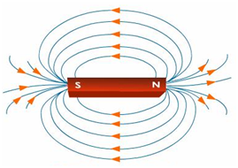
The region around a magnet where its magnetic influence can be experienced is called a magnetic field. The direction and strength of a magnetic field are represented by magnetic lines of force.
Iron filings test around a bar magnet
Iron filings around a bar magnet exhibit the magnetic field lines that engirdle the bar magnet. The magnetic field lines can be explained as imaginary lines that graphically represents the magnetic field that is acting around any magnetic substance.

Magnetic field lines
- Magnet’s magnetic field lines result in the formation of continuous/running closed loops.
- The tangent to the field line at any given point indicates the direction of the total magnetic field at that point.
- The greater the number of field lines crossing per unit area, the higher the intensity, the stronger the magnitude of the magnetic field.
- There is no intersection between the magnetic field lines.

Magnetic field lines for a closed loop
Since magnets have dipoles, magnetic field lines must originate and end. Therefore by convention, it starts at the north pole and moves towards the south pole outside the bar magnet and from south → north inside the magnet. Hence, it forms closed loops.
No two magnetic field lines intersect
Magnetic field lines do not intersect as there will be two tangential magnetic field directions associated with the same point, which does not occur. If a compass needle is placed at that point, it will show two different directions of the magnetic field which is absurd.
Relative strength of magnetic field inferred from magnetic field lines
The closer or denser the magnetic field lines, greater is the magnetic field’s strength.
Magnetic Field Due to a Current Carrying Conductor
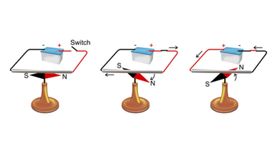
Oersted’s experiment
When electric current flows through a current carrying conductor, it produces a magnetic field around it. This can be seen with the help of a magnetic needle which shows deflection. The more the current, the higher the deflection. If the direction of current is reversed, the direction of deflection is also reversed.
Electromagnetism and electromagnet
An electromagnet is an artificial magnet which produces a magnetic field on the passage of electric current through a conductor. This field disappears when the current is turned off. The phenomenon of producing or inducing a magnetic field due to the passage of electric current is called electromagnetism.
Magnetic field due to a straight current carrying conductor
When current is passed through a straight current-carrying conductor, a magnetic field is produced around it. Using the iron filings, we can observe that they align themselves in concentric circles around the conductor.

Right-hand thumb rule
If a straight conductor is held in the right hand in such a way that the thumb points along the direction of the current, then the tips of the fingers or the curl of the fingers show the direction of magnetic field around it.

Magnetic field due to current through a circular loop
The right-hand thumb rule can be used for a circular conducting wire as well as it comprises of small straight segments. Every point on the wire carrying current gives rise to a magnetic field that appears as straight lines at the centre.

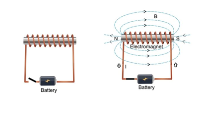
Magnetic field due to current in a solenoid
A solenoid is a coil of many circular windings wrapped in the shape of a cylinder. When current is passed through it, it behaves similar to a bar magnet, producing a very similar field pattern as that of a bar magnet. To increase the strength a soft iron core is used.

Force on a Current Carrying Conductor in a Magnetic Field
Ampere’s experiment
When an electric conductor is placed in a magnetic field, it experiences a force. This force is directly proportional to the current and is also perpendicular to its length and magnetic field.

Force on a straight current carrying conductor placed in a magnetic field
Force on a straight current carrying conductor is mutually perpendicular to the magnetic field and the direction of the current.
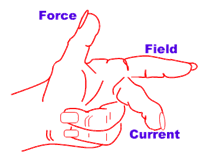
Fleming’s left-hand rule
Fleming’s left hand rule states that the direction of force applied to a current carrying wire is perpendicular to both, the direction of current as well as the magnetic field.
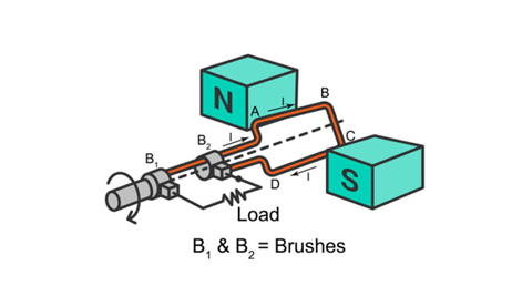
Electric motor
Electric Motor converts electrical energy into mechanical energy.

- Current enters arm AB through brush X and current flows through brush Y from C to D. Using Fleming’s LHR we find that the force pushes AB downwards and pushes CD upwards.
- In an electric motor the split rings PQ act as a commutator that reverses the direction of the current. The reversing of the current is repeated at each half rotation, giving rise to a continuous rotation of the coil.
Electromagnetic Induction and Electric Generators
Faraday’s experiment
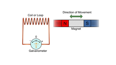
- Faraday discovered that a magnetic field interacts with an electric circuit by inducing a voltage known as EMF (electromotive force) by electromagnetic induction.
- Moving a magnet towards a coil sets up a current in the coil circuit, as indicated by deflection in the galvanometer needle.
Electromagnetic induction
The phenomenon of electromagnetic induction is the production of induced EMF and thereby current in a coil, due to the varying magnetic field with time. If a coil is placed near a current-carrying conductor, the magnetic field changes due to a change in I or due to the relative motion between the coil and conductor. The direction of the induced current is given by Fleming’s right-hand rule.
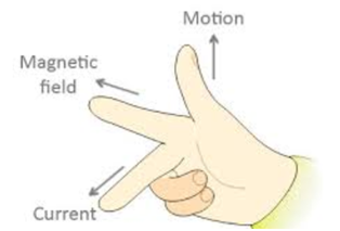
Fleming’s right-hand rule
According to Fleming’s right-hand rule, the thumb, forefinger and middle finger of the right hand are stretched to be perpendicular to each other as indicated below. If the thumb indicates the direction of the movement of conductor, fore-finger indicating direction of the magnetic field, then the middle finger indicates direction of the induced current.
Electric generator
- The device that converts mechanical energy into electrical energy.
- Operates on the principle of electromagnetic induction.
- AC Generation: The axle attached to the two rings is rotated so that the arms AB and CD move up and down respectively in the produced magnetic field. Thus, the induced current flows through ABCD.
- After half rotation the direction of current in both arms changes. Again by applying Fleming’s right hand rule, the induced currents are established in these arms along directions DC and BA, therefore the induced I flows through DCBA.
- DC Generation: They work just like AC, instead use half rings to produce current in one direction only without variations in magnitude.
Domestic Electric Circuits
Fuse
- Fuse is a protective device in an electrical circuit in times of overloading.
- Overloading is caused when the neutral and live wire come in contact due to damage to the insulation or a fault in the line.
- In times of overloading the current in circuit increases (short circuit) and becomes hazardous. Joule’s heating (resistive or ohmic heating on the passage of current) in the fuse device melts the circuit and breaks the flow of current in the circuit.


Domestic electric circuits
- Livewire has a voltage of 220 V and is covered with red insulation.
- Earth wire has a voltage of 0 V (same as Earth) and is covered with green insulation.
- The neutral wire has black insulation.
- In our houses, we receive AC electric power of 220 V with a frequency of 50 Hz.

Power loss in transmission
Power losses in transmission lines over long distances occur due to Joule’s heating. This heat (H)∝l2R causes losses where R is the line resistance.