
- The Hooke’s law is applicable to all elastic substances.
- It does not apply to plastic deformation.
- Mathematically :
- stress ∝ strain
- stress = k × strain
- Where k is the proportionality constant and is known as modulus of elasticity.
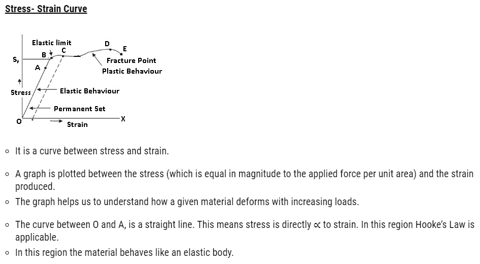
- In the region from A to B, stress and strain are not directly ∝. But still the material returns to its original dimension after the force is removed. They exhibit elastic properties.
- The point B in the curve is known as yield point (also known as elastic limit) which means till this point the material will be elastic in behaviour and the stress corresponding to point B is known as yield strength (Sy) of the material.
- The region between O and B is called as Elastic region.
- From point B to point D we can see that strain increases rapidly even for small change in stress.
- Even if we remove the force the material does not come back to its original position. At this point stress is zero but strain is not zero as body has changed its shape.
- The material has undergone plastic deformation.
- The material is said to be permanent set.
- The point D on the graph is known as ultimate tensile strength (Su) of the material.
- From D to E we can see that stress decreases even if strain increases.
- Finally at point E fracture occurs. This means the body breaks.
- Conclusion:-
- An object is brittle if D and E are very close. This means fracture point is near to tensile strength.
- For example:-Glass which is brittle.

Elastic Modulus
- Elastic modulus is ratio of stress and strain.
- Elastic modulus is a characteristic value of each material. This means gold will have specific value of elastic modulus and rubber will have specific value of elastic modulus etc.
- k=Stress/Strain where k= Elastic modulus.
Problem: – A piece of copper having a rectangular cross-section of 15.2 mm × 19.1 mm is pulled in tension with 44,500 N forces, producing only elastic deformation. Calculate the resulting strain?
Answer:
Length of the piece of copper, l = 19.1 mm = 19.1 × 10⁻³ m
Breadth of the piece of copper, b = 15.2 mm = 15.2 × 10⁻³ m
Area of the copper piece:
A = l × b = 19.1 × 10–3 × 15.2 × 10–3 = 2.9 × 10⁻⁴ m2
Tension force applied on the piece of copper, F = 44500 N
Modulus of elasticity of copper, η = 42 × 109 N/m2
Modulus of elasticity, η = Stress/Strain
= (F/A)/Strain
Strain = F/ (A η) =44500/2.9×10–4x42x109
= 3.65 × 10⁻³
Types of Elastic Modulus
- Young’s Modulus
- Shear Modulus
- Bulk Modulus
Young’s Modulus
- Young’s modulus is derived from the name of the scientist who defined it.
- It is the ratio of longitudinal stress to longitudinal strain.
- It is denoted by Y.
- Mathematically:
- Y= longitudinal stress/ longitudinal strain = σ/ ε
- = (F/A)/ (ΔL/L)
- Y=FL/ΔL
- If Young’s modulus is more, to produce a small change in length more force required.
- S.I. Unit is N m–2 or Pascal (Pa).
- Metals have comparatively greater Young’s Modulus. To change the length of metals, greater force is required.
Problem: – A copper wire of length 2.2 m and a steel wire of length 1.6 m, both of diameter 3.0 mm, are connected end to end. When stretched by a load, the net elongation is found to be 0.70 mm. Obtain the load applied.
Answer:- The copper and steel wires are under a tensile stress because they have the same tension (equal to the load W) and the same area of cross-section A.
Stress = strain × Young’s modulus. Therefore
W/A = Yc × (ΔLc/Lc) = Ys × (ΔLs/Ls) where
The subscripts c and s refer to copper and stainless steel respectively. Or,
ΔLc /ΔLs = (Ys/Yc) × (Lc /Ls)
Given Lc = 2.2 m, Ls = 1.6 m, Yc = 1.1 × 10¹¹ Nm–2, and Ys = 2.0 × 10¹¹ Nm–2.
ΔLc/ΔLs = (2.0 × 10¹¹/1.1 × 1011) × (2.2/1.6) = 2.5.
The total elongation is given to be
ΔLc + ΔLs = 7.0 × 10⁻⁴ m
Solving the above equations,
ΔLc = 5.0 × 10⁻⁴ m, and ΔLs = 2.0 × 10⁻⁴ m.
Therefore
W = (A × Yc × ΔLc)/Lc
= π (1.5 × 10⁻³)2 × [(5.0 × 10-4 × 1.1 × 1011)/2.2]
= 1.8 × 10² N
Problem: A structural steel rod has a radius of 10 mm and a length of 1.0 m. A 100 kN force stretches it along its length. Calculate (a) stress, (b) elongation, and (c) strain on the rod. Young’s modulus, of structural steel is 2.0 × 10¹¹ N m-2.
Answer: We assume that the rod is held by a clamp at one end, and the force F is applied at the other end, parallel to the length of the rod.
Then the stress on the rod is given by
Stress =F/A = F/πr2
=100 103 N/3.14 102 m2
= 3.18 × 10⁸ N m–2
The elongation,
ΔL = (F/A) Y
= (3.18 108 N m-2 1m)/ (2 1011 N m-2)
= 1.59 × 10⁻³ m
= 1.59 mm
The strain is given by
Strain = ΔL/L
= (1.59 × 10⁻³ m)/ (1m)
= 1.59 × 10–3
= 0.16 %
Young’s Modulus: Application
- In industrial constructions steel is preferred over copper. The reason behind this is steel is more elastic than copper.
- If there is slight deformation in steel due to contraction and expansion it will come back to its original position.
- Steel is preferred over copper to construct bridges.

Problem:- A steel wire of length 4.7 m and cross-sectional area 3.0 × 10⁻⁵ m2 stretches by the same amount as a copper wire of length 3.5 m and cross-sectional area of 4.0 × 10⁻⁵m2, under a given load. What is the ratio of the Young’s modulus of steel to that of copper?
Answer:- Length of the steel wire, L1 = 4.7 m
Area of cross-section of the steel wire, A1 = 3.0 × 10⁻⁵m2
Length of the copper wire, L2 = 3.5 m
Area of cross-section of the copper wire, A2 = 4.0 × 10⁻⁵m2
Change in length = ΔL1 = ΔL2 = ΔL
Force applied in both the cases = F
Young’s modulus of the steel wire:
Y1 = (F1/A1) (L1/ ΔL)
=F x 4.7/ (3.0 × 10⁻⁵x ΔL) … (i)
Young’s modulus of the copper wire:
Y2 = (F2/A2) (L2/ ΔL)
= F x3.5/ (4.0 × 10⁻⁵x ΔL) … (ii)
Dividing (i) by (ii), we get:
Y1/Y2 = (4.7×4.0 × 10–5)/ (3.0 × 10–5x3.5)
=1.79:1
The ratio of Young’s modulus of steel to that of copper is 1.79: 1.
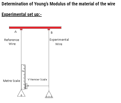
- Two strings were hung from a support and two pans were attached to both the strings.
- Weights are kept on both the pans.
- When the number of weights in second pan was increased, the string got stretched and moved in downward direction.
- The change in length was measured by the metre scale which was kept on reference wire.
- Using this experiment, the Young’s modulus value was calculated
- Y= longitudinal stress/ longitudinal strain = σ/ ε
- = (F/A)/ (ΔL/L)
- Where original length = L and ΔL = change in length, F=mg (acting downwards) and A (area of cross-section of wire) = πr2
- = (mg/ πr2)/ (ΔL/L)
- Y= mgL/ πr2 ΔL
- This is the way to calculate the Young’s modulus.
Problem:- Read the following two statements below carefully and state, with reasons, if it is true or false.
- a) The Young’s modulus of rubber is greater than that of steel;
- b) The stretching of a coil is determined by its shear modulus.
Answer:
(a) False
(b) True
For a given stress, the strain in rubber is more than it is in steel.
Young’s modulus, Y = 𝑆𝑡𝑟𝑒𝑠𝑠/𝑆𝑡𝑟𝑎𝑖𝑛
For a constant stress: 𝑌 ∝ 1/𝑆𝑡𝑟𝑎𝑖𝑛
Hence, Young’s modulus for rubber is less than it is for steel.
Shear modulus is the ratio of the applied stress to the change in the shape of a body. The stretching of a coil changes its shape. Hence, shear modulus of elasticity is involved in this process.
Problem:- A rigid bar of mass 15 kg is supported symmetrically by three wires each 2.0 m long. Those at each end are of copper and the middle one is of iron. Determine the ratio of their diameters if each is to have the same tension.
Answer:- The tension force acting on each wire is the same.
Thus, the extension in each case is the same. Since the wires are of the same length, the strain will also be the same.
The relation for Young’s modulus is given as:
Y =𝑆𝑡𝑟𝑒𝑠𝑠/𝑆𝑡𝑟𝑎𝑖𝑛 = (F/A)/Strain = (4F/ πd2)/Strain Equation (i)
Where,
F = Tension force
A = Area of cross-section
D=Diameter of the wire
From equation (i) Y ∝ 1/d2
Young’s Modulus for iron, Y1 =190×109 Pa
Diameter of the iron wire =d1
Young’s Modulus for copper, Y2 = 110×109 Pa
Diameter of the copper wire =d2
Therefore the ratios of their diameters are given as:
d1/ d2 =√ Y1/ Y2 =√190×109/110×109 = √19/11 =1.31:1
Shear Modulus (Modulus of Rigidity)
- Shear modulus is defined as shearing stress to shearing strain.
- It is also known as Modulus of Rigidity.
- It is denoted by ‘G’.
- S.I. Unit: N/m2 or Pascal(Pa)
- Mathematically
- G=shearing stress/shearing strain = (F/A)/( Δx/L) = FL/A Δx
- By the definition of shearing strain 1/ θ =(L/ Δx)
- G=F/A θ
Relation between Young’s Modulus and Shear Modulus
- Shear modulus is less than Young’s modulus.
- For most materials G = Y/3.
Problem:- A box shaped piece of wax has a top area of 10cm2 and height of 2cm.When a shearing force of 0.5N is applied to the upper surface, displaces 4mm relative to the bottom surface. What are the shearing stress, shearing strain and shear modulus for wax?
Answer:- Area = 10cm2, height =2cm, (displacement) x=4mm
- Shearing stress = tangential force/Area
=0.5/10×10-4 = 500Pa
- Shearing strain = small displacement/initial length = x/L
= (4×10⁻³)/ (2×10⁻²) = 0.2
- Shear Modulus = Shearing stress/ Shearing strain
=500/0.2 = 2500 Pa.
Problem:- A square lead slab of side 50 cm and thickness 10 cm is subject to a
shearing force (on its narrow face) of 9.0 × 10⁴ N. The lower edge is riveted to the floor. How much will the upper edge are displaced?
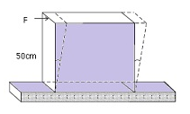
Answer: – The lead slab is fixed and the force is applied parallel to the narrow face as shown in Fig. The area of the face parallel to which this force is applied is
A = 50 cm × 10 cm
= 0.5 m × 0.1 m
= 0.05 m2
Therefore, the stress applied is
= (9.4 × 10⁴ N/0.05 m2)
= 1.80 × 10⁶Nm–2
We know that shearing strain = (Δx/L) = Stress /G. Therefore the displacement Δx = (Stress × L)/G = (1.8 × 10⁶ N m–2 × 0.5m)/ (5.6 × 10⁹ N m–2)
= 1.6 × 10⁻⁴ m = 0.16 mm
Problem:- The edge of an aluminium cube is 10 cm long. One face of the cube is firmly fixed to a vertical wall. A mass of 100 kg is then attached to the opposite face of the cube. The shear modulus of aluminium is 25 GPa. What is the vertical deflection of this face?
Answer:
Edge of the aluminium cube, L = 10 cm = 0.1 m
The mass attached to the cube, m = 100 kg
Shear modulus (η) of aluminium = 25 GPa = 25 × 109 Pa
Shear modulus, η = Shear stress/Shear Strain = (F/A)/L/ ΔL
Where,
F = Applied force = mg = 100 × 9.8 = 980 N
A = Area of one of the faces of the cube = 0.1 × 0.1 = 0.01 m2
ΔL = Vertical deflection of the cube
ΔL = FL/A η = (980×0.1)/10-2x (25×109)
= 3.92 × 10⁻⁷ m
The vertical deflection of this face of the cube is 3.92 ×10⁻⁷ m.
Bulk Modulus
- Bulk modulus is the ratio of hydraulic stress to the corresponding hydraulic strain.
- Denoted by ‘B’
- B = -p/(ΔV/V)
- Where p =hydraulic stress, ΔV/V = hydraulic strain
(-) ive signs show that the increase in pressure results in decrease in volume.
- S.I. Unit :- N/m2 or Pascal(Pa)
- B(solids) > B(liquids) >B(gases)