Pascal’s law for transmission of fluid pressure
- Pascal’s law for transmission of fluid pressure states that thepressure exerted anywhere in a confined incompressible fluid is transmitted undiminished and equally in all directions throughout the fluid.
- The above law means that if we consider a fluid which is restricted within a specific region in space and if the volume of the fluid doesn’t change with the pressure,then the amount of pressure exerted will be same as the amount of pressure transmitted.
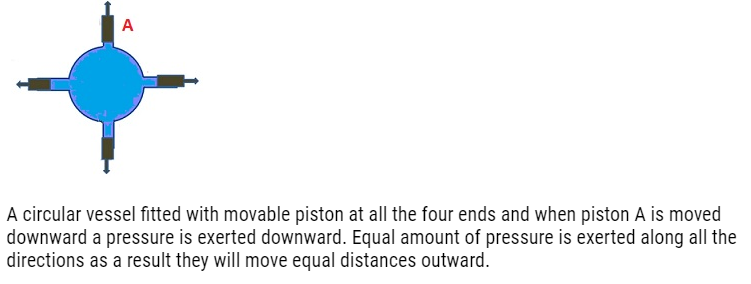
- Consider a circular vessel which have 4 openings and along these 4 openings 4 pistons are attached.
- When piston A is moved downwards pressure is exerted on the liquid in the downward direction, this pressure gets transmitted equally along all the directions. As a result all the other 3 pistons move equal distance outwards.
Applications:Pascal’s law for transmission of fluid pressure
Hydraulic lift:-
- Hydraulic lift is a lift which makes use ofa fluid.
- For example: Hydraulic lifts that are used in car service stations to lift the cars.
- Principle: –
- Inside a hydraulic lift there are 2 platforms,one has a smaller area and the other one has a larger area.
- It is a tube like structure which is filled with uniform fluid.
- There are 2 pistons (P1 and P2)which are attached at both the ends of the tube.
- Cross-sectional area of piston P1 is A1 and of piston P2 is A2.
- If we apply force F1 on P1, pressure gets exerted and according to Pascal’s law the pressure gets transmitted in all the directions and same pressure gets exerted on the other end.As a result the Piston P2 moves upwards.
- Advantage of using hydraulic lift is that by applying small force on the small area we are able to generate a larger force.
- Mathematically:- F2=PA2
- where F2 = Resultant Force,A2 = area of cross-section
- F2= (F1/A1)A2 where P=F1/A1 (Pressure P is due to force F1 on the area A1)
- F2 =(A2/A1)F1. This shows that the applied force has increased by A2/A1.
- Because of Pascal’s law the input gets magnified.

Problem: A hydraulic automobile lift is designed to lift cars with a maximum mass of 3000 kg. The area of cross-section of the piston carrying the load is 425 cm2. What maximum pressure would the smaller piston have to bear?
Answer:-
The maximum mass of a car that can be lifted, m = 3000 kg
Area of cross-section of the load-carrying piston, A = 425 cm2 = 425 × 10–4 m2
The maximum force exerted by the load,
F = mg = 3000 × 9.8 = 29400 N
The maximum pressure exerted on the load-carrying piston, P = F/A
=29400/425×105
= 6.917 × 10⁵ Pa
Pressure is transmitted equally in all directions in a liquid. Therefore, the maximum
pressure that the smaller piston would have to bear is 6.917 × 10⁵ Pa.
Hydraulic Brakes
- Hydraulic brakes work on the principle of Pascal’s law.
- According to this law whenever pressure is applied on a fluid it travels uniformly in all the directions.
- Therefore when we apply force on a small piston, pressure gets created which is transmitted through the fluid to a larger piston. As a result of this larger force,uniformbrakingis applied on all four wheels.
- As braking force is generateddue to hydraulic pressure,theyare known as hydraulic brakes.
- Liquids are used instead of gas as liquids are incompressible.
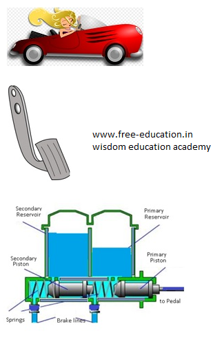
Construction
- The fluid in the hydraulic brake is known as brake fluid.
- It consists of a master cylinder, four wheel cylinders and pipes carrying brake fluid from master cylinder to wheel cylinders.
- Master cylinder consists of a piston which is connected to pedal through connecting rod.
- The wheel cylinders consist of two pistons between which fluid is filled.
- Each wheel brake consists of a cylinder brake drum. This drum is mounted on the inner side of wheel. The drum revolves with the wheel.
- Two brake shoes whichare mounted inside the drum remain stationary.
Working
- When we press the brake pedal, piston in the master cylinder forces the brake fluid through a linkage.
- As a result pressure increases and gets transmitted to all the pipes and to all the wheel cylinders according to Pascal’s law.
- Because of this pressure,both the pistons move outand transmit the braking force on all the wheels.
Advantages:-
- Equal braking effort to all the four wheels.
- Less rate of wear due to absence of joints.
- By just changing the size of one piston and cylinder, force can be increased or decreased.
Disadvantages:-
- Leakage of brake fluid spoils the brake shoes.
- Even the slightest presence of air pockets can spoil the whole system.
Problem:- Two syringes of differentcross sections (without needles) filled withwater are connected with a tightly fittedrubber tube filled with water. Diametersof the smaller piston and larger piston are1.0 cm and 3.0 cm respectively. (a) Findthe force exerted on the larger piston whena force of 10 N is applied to the smallerpiston. (b) If the smaller piston is pushed in through 6.0 cm, how much does thelarger piston move out?
Answer:
- Since pressure is transmitted undiminished throughout the fluid,
F2 = (A2/A1) F1= (3/2 10-2m2/1/2 10m-2 m2) 10N
=90N.
(b) Water is considered to be perfectlyincompressible. Volume covered by themovement of smaller piston inwards is equal tovolume moved outwards due to the larger piston.
L1 A1 = L2 A2
= 0.67 × 10⁻² m = 0.67 cm
Note, atmospheric pressure is common to bothpistons and has been ignored.
Problem:- In a car lift compressed airexerts a force F1 on a small piston havinga radius of 5.0 cm. This pressure istransmitted to a second piston of radius 15 cm. If the mass of the car tobe lifted is 1350 kg, calculate F1. What isthe pressure necessary to accomplish thistask? (g = 9.8 ms-2).
Answer:-
Since pressure is transmittedundiminished throughout the fluid,
F1=A1/A2 F2
= (5×10⁻² m2/15×10-2m2) 1350N x 9.8ms-2
=1470N = 1.5×10³N
The air pressure that will produce thisforce is
P=F1/A1 = (1.5×10³N/5×10-2m2)1.9×105 Pa
This is almost double the atmosphericpressure.
Types of Fluid flow: Steady Flow
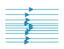
Some streamlines for fluid flow
- The flow of a fluid is said to be steady, if at any point,the velocity of each passing fluid particle remains constant within that interval of time.
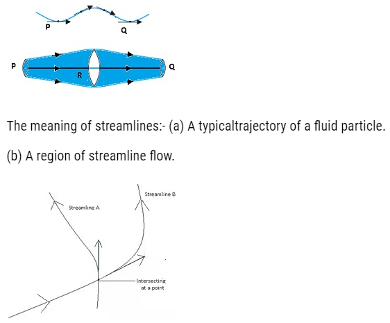
- Streamline is the path followed by the fluid particle.
- It means that at any particular instant the velocities of all the particles at any point are same.But the velocity of all the particles won’t be same across all the points in the space.
- Steady flow is termed as ‘Streamline flow’ and ‘Laminar flow’.
- Consider a case when all the particles of fluid passing point A have the same velocity. This means that the first particle will have velocity V1 and second will have velocity V1 and so on. All the particles will have the same velocity V1at point A.
- At point B,all particleswill have velocity V2.
- Similarly at point C the velocity of all the particles is V3.
- We can see that the velocity is changing from point to point but at one particular point it is same.
- No two streamlines can intersect.
- If two streamlines intersect each other, the particleswon’t know which path to follow and what velocity to attain.That is why no two streamlines intersect.
Equation of Continuity
- According to the equation of continuity Av = constant. Where A =cross-sectional area and v=velocity with which the fluid flows.
- It means that if any liquid is flowing in streamline flow in a pipe of non-uniform cross-section area, then rate of flow of liquid across any cross-section remains constant.
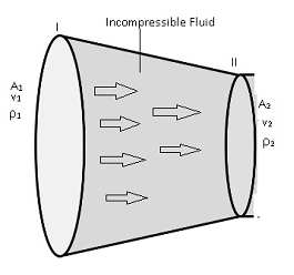
- Consider a fluid flowing through a tube of varying thickness.
- Let the cross-sectional area at one end (I) = A1 and cross-sectional area of other end (II)= A2.
- The velocity and density of the fluid at one end (I)=v1,ρ1respectively, velocity and densityof fluid at other end (II)= v2,ρ2
- Volume covered by the fluid in a small interval of time ∆t,across left cross-sectional is Area (I) =A1xv1x∆t
- Volume covered by the fluid in a small interval of time ∆tacrossright cross-sectional Area(II) = A2x v2x∆t
- Fluid inside is incompressible(volume of fluid does not change by applying pressure) that is density remains sameρ1=ρ2. (equation 1)
- Along(I) mass=ρ1 A1 v1∆t and along second point (II) mass = ρ2A2 v2∆t
- By using equation (1). We can conclude that A1 v1 = A2 v2.This is the equation of continuity.
- From Equation of continuity we can say that Av=constant.
- This equation is also termed as “Conservation of mass of incompressible fluids”
Conclusion:
- Volume flux/Flow rate remains constant throughout the pipe. This means rate of flow of fluid of liquidis more if cross-sectional area is more, then the velocity will be less,andvice-versa.
- But the Av will remain constant.
- So the volume which is covered by the fluid at any cross-sectional area is constant throughout the pipe even if pipe has different cross-sectional areas.
- The fluid is accelerated while passing from the wider cross sectional area towards the narrower area. This means if area is more the velocity is less and vice-versa.
Problem: – The cylindrical tube of a spray pump has a cross-section of 8.0 cm2 one end of which has 40 fine holes each of diameter 1.0 mm. If the liquid flow inside the tube is 1.5 m min–1, what is the speed of ejection of the liquid through the holes?
Answer:-
Area of cross-section of the spray pump, A1 = 8 cm2 = 8 × 10⁻⁴ m2
Number of holes, n = 40
Diameter of each hole, d = 1 mm = 1 × 10⁻³ m
Radius of each hole, r = d/2 = 0.5 × 10⁻³ m
Area of cross-section of each hole, a = πr2 = π (0.5 × 10⁻³)2 m2
Total area of 40 holes, A2 = n × a = 40 × π (0.5 × 10⁻³)2 m2
= 31.41 × 10⁻⁶ m2
Speed of flow of liquid inside the tube, V1 = 1.5 m/min = 0.025 m/s
Speed of ejection of liquid through the holes = V2
According to the law of continuity, we have:
A1V1=A2V2
V2= A1V1/ A2
= (8 × 10–4x0.025)31.61×10-6
= 0.633 m/s
Therefore, the speed of ejection of the liquid through the holes is 0.633 m/s.
Turbulent Flow:
- A fluid flow is said to be turbulent if the velocity of the particles vary at any point erratically.
- This means fluid particles are moving here and there, they are not moving in organised manner. They all will have different velocities.
- Eddies are generated by this flow.Eddies are same as ripples.
- All the particles are moving here and there randomly.